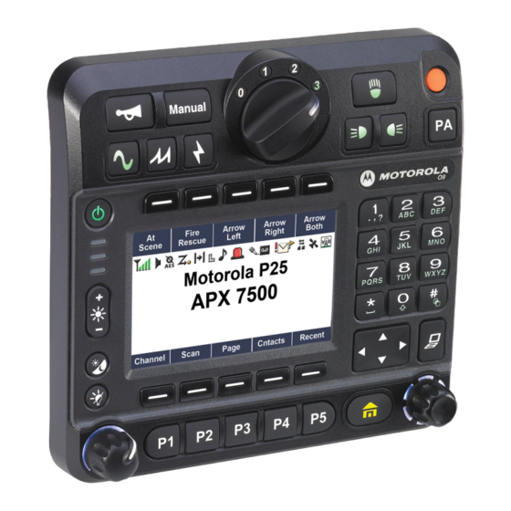
Motorola ASTRO APX O9 Installation Manual - Page 15
Browse online or download pdf Installation Manual for Radio Motorola ASTRO APX O9. Motorola ASTRO APX O9 25 pages. Control head mobile radio
Also for Motorola ASTRO APX O9: Quick Reference Manual (44 pages)

Mobile Radio Model Numbering Scheme
Mobile Radio Model Numbering Scheme
Typical Model Number:
Position:
Position 1 - Type of Unit
M = Mobile
L = Table Top Station
Positions 2 & 3 - Model Series
Model Series
30 = APX 7500
25 = APX 6500
36 = APX1500
Position 4 - Frequency Band
A
=
Less than 29.7MHz
B
=
29.7 to 35.99MHz
C
=
36 to 41MHz
D
=
42 to 50MHz
E
=
300 to 345MHz
F
=
66 to 80MHz
G
=
74 to 90MHz
H
=
Product Specific
VHF Range
J
=
136 to 162MHz
K
=
146 to 178MHz
L
=
174 to 210MHz
M
=
190 to 235MHz
* For APX 7500 "K" in Position 4 represents
136-174MHz.
* For APX 7500 "Q" in Position 4 represents
380-470MHz.
* For APX 7500 "S" in Position 4 represent
470-520MHz.
* For APX 7500 "U" in Position 4 represent
762-870MHz.
Note: Values represented are not absolute,
and are given to indicate range only .
Position 5 - Power Level
A
=
0 to 0.7 Watts
B
=
0.7 to 0.9 Watts
C
=
1.0 to 3.9 Watts
D
=
4.0 to 5.0 Watts
E
=
5.1 to 6.0 Watts
F
=
6.1 to 10 Watts
G
=
10.1 to 15 Watts
H
=
16 to 25 Watts
J
=
26 to 35 Watts
Note: Values represented are not absolute ,
and are given to indicate range only .
Position 6 - Physical Packages
A
=
RF Modem Operation
B
=
Receiver Only
C
=
Standard Control; No Display
D
=
Standard Control; With Display
E
=
Limited Keypad; No Display
F
=
Limited Keypad; With Display
G
=
Full Keypad; No Display
H
=
Full Keypad; With Display
J
=
Limited Controls; No Display
K
=
Limited Controls; Basic Display
L
=
Limited Controls; Limited Display
M
=
Rotary Controls; Standard Display
N
=
Enhanced Controls; Enhanced Display
P
=
Low Profile; No Display
Q
=
Low Profile; Basic Display
R
=
Low Profile; Basic Display , Full Keypad
S
=
Tranceiver with Selectable Control Head
T
=
U
=
V
=
VDV Control Head
W
=
Control Head #2
Position 7 - Channel Spacing
0 =
1 = 5KHz
2 = 6.25KHz
3 = 10KHz
4 = 12.5KHz
MN003109A01_aa
M
3
7
T
S
1
2
3
4
5
24 = APX 2500
22 = APX 4500
37 = APX 8500
UHF Range
N
=
330 to 370MHz
P
=
366 to 410MHz
Q
=
403 to 437MHz
R
=
438 to 482MHz
S
=
470 to 620MHz
T
=
Product Specific
806 to 870MHz*
U
=
=
825 to 870MHz
V
=
896 to 941MHz
z
W
403-470MHz
Hz
=
X
=
1.0 to 1.6GHz
6GHz
Y
=
1.5 to 2.0GHz
2.0GH
Z
epresen
n 4 rep
represe
ent
K
=
36 to 60 Watts
L
=
61 to 110 Watts
M
=
Up to 125 Watts
N
=
1 to 25 Watts
P
=
25 to 40 Watts
Q
=
25 to 45 Watts
R
=
10 to 35 Watts
S
=
10 to 50 Watts
T
=
25 to 110 Watts
5 = 15KHz
6 = 20/25KHz
7 = 30KHz
8 = 12.5/25KHz
9 = Variable/Programmable
S
9
P
W
1
A
6
7
8
9
10
11
Position 11 - Version
Version Letter (Alpha) - Major Change
Position 10 - Feature Level
1 = Basic
2 = Limited Package
3 = Limited Plus
4 = Intermediate
5 = Standard Package
Position 9 - Primary System Type
A
=
Conventional
B
=
Privacy Plus
C
=
Clear SMARTNET
D
=
Advanced Conventional Stat-Alert
E
=
Enhanced Privacy Plus
F
=
Nauganet 888 Series
G
=
Japan Specialized Mobile Radio (JSMR)
H
=
Multi-Channel Access (MCA)
J
=
CoveragePLUS
K
=
MPT1327* - Public
L
=
MPT1327* - Private
M
=
Radiocom
N
=
Tone Signalling
P
=
Binary Signalling
Q
=
Phonenet
hone
R
R
=
=
IDEN Ba
IDEN Basic
S
S
=
=
IDEN Adv
IDEN Advanced Feature
T
T
=
=
JSMR Digital
JSMR Digita
U
U
=
LTR Protocol
TR Proto
V
=
Single Sideband
Single Sid
W
=
=
Programmable
Programm
X
X
=
=
Se
Secure Conventional
Y
Y
=
=
Secure SMARTNET
Z
Z
=
TETRA
2
2
=
SmartZone
* MPT = Ministry of Posts and Telecommunications
Position 8 - Primary Operation
=
A
Conventional/Simplex
=
B
Conventional/Duplex
=
C
Trunked Twin Type
=
D
Dual Mode Trunked
=
E
Dual Mode Trunked/Duplex
=
F
Trunked Type I
=
G
Trunked Type II
=
H
FDMA* Digital Dual Mode
=
J
TDMA** Digital Dual Mode
=
K
Single Sideband
=
L
Global Positioning Satellite Capable
=
M
Amplitude Companded Sideband (ACSB)
=
N
Digital Dispatch
=
P
Programmable
=
Q
Digital Interconnect
=
R
Digital Multi-Service
=
S
9600 Capable
=
T
TDMA
* FDMA = Frequency Division Multiple Acces s
** TDMA = Time Division Multiple Access
N
S
P
0
1
12 13
14
15
16
Positions 13 - 16
SP Model Suffix
Position 12 -
Unique Model Variations
C = Cenelec
N = Standard Package
6 = Standard Plus
7 = Expanded Package
8 = Expanded Plus
9 = Full Feature/
Programmable
xiii
