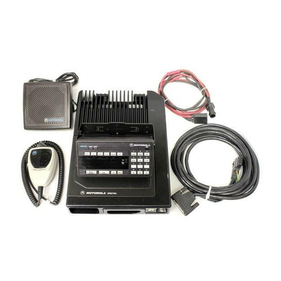
Motorola ASTRO Digital Spectra Installation Manual - Page 15
Browse online or download pdf Installation Manual for Radio Motorola ASTRO Digital Spectra. Motorola ASTRO Digital Spectra 32 pages. Fm two-way mobile radios
Also for Motorola ASTRO Digital Spectra: Parts List (13 pages)

Remote Radio
Control Cable
Installation
Remove the fuse from the fuseholder and connect the short red cable with
the fuse connection to the positive battery terminal. Cut the long red radio
power cable to the proper length and strip the red insulation back 3/4" from
the end. Slide the heat-shrink tubing provided with the equipment over the
cable. Insert the stripped end into the fuse receptacle (assembly shown in
Figure 9), and solder it for a good electrical connection. After soldering has
been completed, slide the heat-shrink tubing over the solder joint and
apply heat. DO NOT install the fuse until instructed to do so.
Connect the red cable from the fuseholder to the positive battery terminal.
Connect the black radio power lead, from the radio, to a good ground
connection on the vehicle chassis. DO NOT connect the black radio power
lead directly to the battery's negative terminal.
TO RADIO
Figure 9 High-Power Main Fuse Assembly (40-Amp)
Exploded View Parts List
Fuse Assembly for High-Power Main Fuse (40-Amp)
REFERENCE
SYMBOL
1
2
3
4
5
6
The radio control cable should go from the rear of the control head to the
radio. Route the cables in the vehicle's wiring troughs (where available) or
route the cables where they are protected from pinching, sharp edges, or
crushing. One suggested route is along one side of the driveshaft hump
under the carpet. Use grommets in any holes where the cable passes
through metal panels. Figure 8 shows how the cables and components are
connected.
3
4
5
1
6
MOTOROLAP
ART NO.
0300139931
0984277B02
3884383D02
4284275B01
6584161B01
3700134371
TO POSITIVE
BATTERY TERMINAL
2
MAEPF-21363-O
DESCRIPTION
SCREW
RECEPTACLE, Fuse
CAP, Protective
FUSE, Retainer
FUSE, 40-Amp (5AG)
TUBING, Heat-Shrink
9
