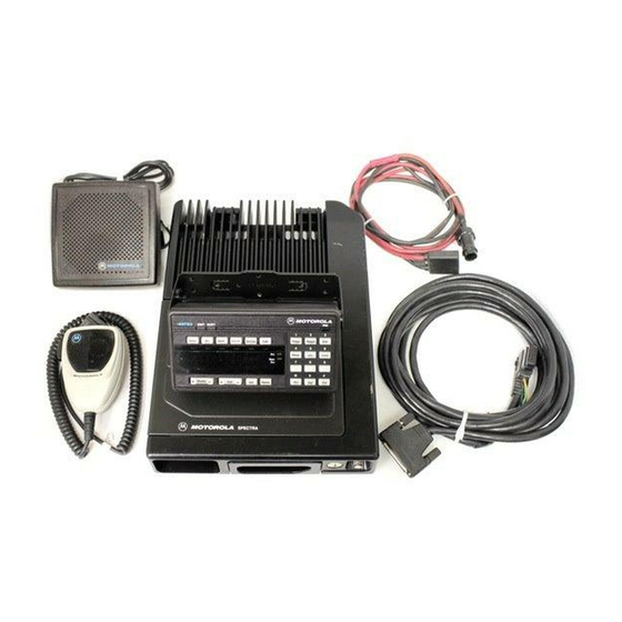
Motorola ASTRO Digital Spectra Installation Manual - Page 22
Browse online or download pdf Installation Manual for Radio Motorola ASTRO Digital Spectra. Motorola ASTRO Digital Spectra 32 pages. Fm two-way mobile radios
Also for Motorola ASTRO Digital Spectra: Parts List (13 pages)

Transmitter Control
Power Lead (Orange)
16
•
Temporarily, install the fuse (both are 3-amp), into the fuse clips onto
both sides of the fuse. Slide the spring over the remaining loose end of
the wire. The spring should be followed by the plastic insulator
fuseholder oriented as shown in Figure 10. Slide the plastic insulator
fuse holder together, by first making sure the spring slips inside the
plastic insulator fuseholder cap. Now, twist the fuseholders until they
lock together. After assembly proves successful, remove the fuses
until instructed to install them later.
With the spring and plastic insulator fuseholder cap still in place on the
loose portion of the wires (orange and green), insert the stripped end of the
wire into the spade or ring tongue lug. Crimp and solder the lug as was
done on the metal fuse clips above.
SPADE OR RING
TONGUE LUG
(RING TONGUE
LUG SHOWN)
PLASTIC INSULATOR
FUSE HOLDER CAP
METAL FUSE
CLIPS CRIMP
AND SOLDER
TO CONTROL
Figure 14 Fuseholder Assembly and Parts List
for Orange and Green Control Cables
Parts List
Fuse Assembly for Orange and Green Leads
MOTOROLA
PART NO.
1482882A01
1482883A01
2900136968
2900824456
2900865065
4182885A01
4282884Q01
6500020404
Connect the orange lead to the ignition switch (recommended) or directly
to the battery hot supply (see Figure 8).
SPRING
TO WIRE
FUSE
HEAD
PLASTIC INSULATOR
FUSE HOLDER
MAEPF-21361-O
DESCRIPTION
INSULATOR, Fuseholder Body
INSULATOR, Fuseholder Cap
LUG
LUG, Ring Tongue
LUG, Ring Tongue
SPRING, Compression; Fuse
CLIP, Fuse
FUSE, 3-Amp 250V (Qty. 2)
