Motorola GP series Service Information - Page 3
Browse online or download pdf Service Information for Radio Motorola GP series. Motorola GP series 24 pages. Professional radio
Also for Motorola GP series: Service Manual (26 pages), Service Information (31 pages), Service Information (43 pages), Service Information (30 pages), User Manual (16 pages), Manual (30 pages)
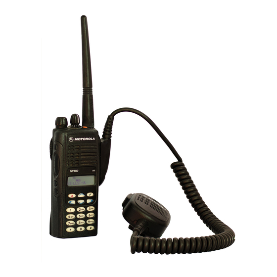
Table of Contents
Chapter 1
1.0 GP340/GP380 Model Chart .................................................................................1-1
2.0 Technical Specifications ......................................................................................1-2
Chapter 2
1.0 Lowband Transmitter ...........................................................................................2-1
1.1 Power Amplifier (PA) ......................................................................................2-1
1.2 Antenna Switch...............................................................................................2-2
1.3 Harmonic Filter ...............................................................................................2-2
1.4 Antenna Matching Network ............................................................................2-2
1.5 Power Control Integrated Circuit (PCIC) ........................................................2-2
1.6 Temperature Cut Back Circuit ........................................................................2-2
2.0 Lowband Receiver ...............................................................................................2-3
2.1 Receiver Front-End ........................................................................................2-3
2.2 Receiver Back-End.........................................................................................2-4
2.3 Automatic Gain Control (AGC) .......................................................................2-5
2.4 Frequency Generation Circuit.........................................................................2-5
3.0 Synthesizer ..........................................................................................................2-6
4.0 Voltage Control Oscillator (VCO) .........................................................................2-7
4.1 Receive VCO..................................................................................................2-7
4.2 Transmit VCO.................................................................................................2-7
4.3 Buffer ..............................................................................................................2-7
4.4 Diplexer and Output Filters.............................................................................2-7
4.5 Prescalar Feedback........................................................................................2-7
Chapter 3
1.0 Receiver (Sheet 1 of 2) ........................................................................................3-1
2.0 Receiver (Sheet 2 of 2) ........................................................................................3-2
3.0 Transmitter...........................................................................................................3-3
4.0 Synthesizer ..........................................................................................................3-4
5.0 Voltage Controlled Oscillator ...............................................................................3-5
Chapter 4
LOWBAND SCHEMATICS
1.0 Allocation of Schematics and Circuit Boards .......................................................4-1
1.1 Controller Circuits ...........................................................................................4-1
2.0 Schematics ..........................................................................................................4-3
3.0 Parts List ............................................................................................................4-12
iii