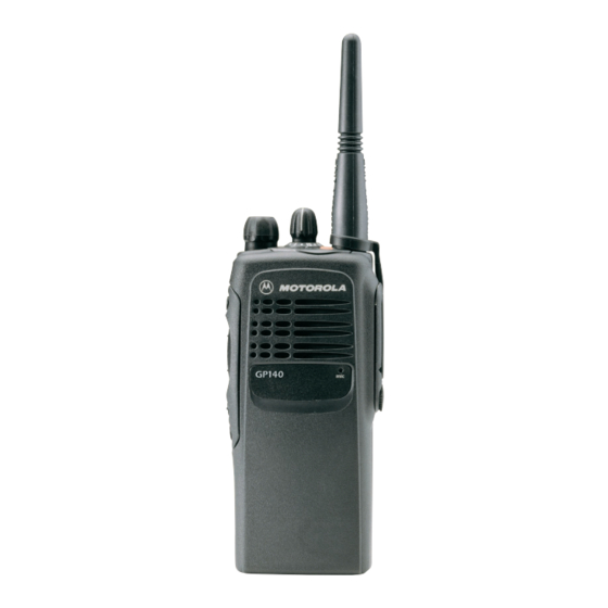
Motorola GP1280 Series Basic Service Manual - Page 38
Browse online or download pdf Basic Service Manual for Radio Motorola GP1280 Series. Motorola GP1280 Series 46 pages. Professional radio, power distribution and controller
Also for Motorola GP1280 Series: Service Information (32 pages), Service Information (30 pages), Service Information (30 pages)

4-2
3.0
Transmitter Performance Tests
The transmitter performance tests are described in Table 4-2 below.
Test Name
Reference
Mode: PWR MON
Frequency
Monitor: Frequency error
Input at RF In/Out
Power RF
As above
Voice
Mode: PWR MON
Modulation
atten to -70, input to RF In/
Out
Monitor: DVM, AC Volts
Set 1kHz Mod Out level for
0.025Vrms at test set,
80mVrms at AC/DC test set
jack
Voice
Mode: PWR MON
Modulation
atten to -70, input to RF In/
(internal)
Out
DTMF
As above,
Modulation
PL/DPL
As above
Modulation
BW to narrow
Table 4-2 Transmitter Performance Checks
Communications
Analyzer
Radio
Test Set
TEST MODE,
PTT to continu-
Test Channel
ous (during the
4 carrier
performance
squelch
check)
As above
As above
As above
As above, meter
selector to mic
TEST MODE,
Remove
Test Channel
modulation
4 carrier
input
squelch out-
put at
antenna
TEST MODE,
As above
Test Channel
4 DTMF out-
put at
antenna
TEST MODE,
As above
Test
Channel 4
TPL
DPL
PERFORMANCE TESTING
Comments
Frequency error to be
± 200Hz VHF
± 600Hz UHF
Refer to Mainte-
nance Specifications
Deviation:
VHF, UHF,
≥ 4.0kHz but
≤ 5.0kHz.
(25 kHz Ch Sp)
Press PTT switch on
radio. Say "four"
loudly into the radio
mic. Measure devia-
tion: VHF, UHF,
≥ 4.0kHz but
≤ 5.0kHz
(25 kHz Ch Sp)
Deviation:
VHF, UHF,
≥ 3.05kHz but
≤ 3.45kHz
(25 kHz Ch Sp).
Deviation:
VHF, UHF,
≥ 500Hz but
≤ 1000Hz.
(25 kHz Ch Sp).
