Motorola GP340 ATEX Service Information - Page 26

Browse online or download pdf Service Information for Radio Motorola GP340 ATEX. Motorola GP340 ATEX 30 pages. Professional radio, power distribution and controller
Also for Motorola GP340 ATEX: Specification Sheet (5 pages), User Manual (31 pages), Specification Sheet (2 pages), User Manual (30 pages), User Manual (30 pages), Basic User's Manual (10 pages), Service Information (32 pages), Service Information (26 pages), Service Information (24 pages), Service Information (31 pages), Service Information (43 pages), Service Information (30 pages)
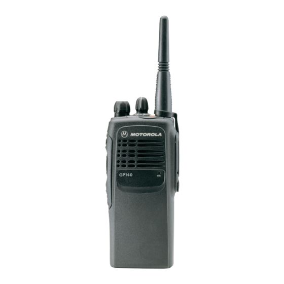
Motorola GP340 ATEX Service Information
3-4
4.0

Troubleshooting Flow Chart for Synthesizer

Check D3701,
Correct
D3702, U3701,
Problem
C3701 - C3707
YES
5V
NO
Is U3701
at pin 6 of
Pin47 AT = 13
D3701
NO
Check
L3701,
R3701
Is
U3701
Pin 19<0.7 VDC
in RX & >4.3 VDC
in TX?
YES
Is
U3701 Pin
18 AT 4.54
VDC?
YES
Is RF level at
U3701 Pin 32
>-30 dBm?
YES
Are
C3721,
C3722,C3723,
R3721, R3722,
R3723
OK?
YES
Replace
U3701
NO
VDC
YES
Check Q260,
Q261 & R260
NO
U3701
YES
pin 2 at >3V
in Tx and
<0.7V in
Rx
NO
NO
Replace
If R3727, C3726 & C3727
NO
are OK, then see VCO
troubleshooting chart
Replace or
NO
resolder
necessary
components
Start
Visual
check of the
Board
OK?
YES
YES
+5V
NO
at U3701
Pin's
13 & 30?
Check 5V
Regulator
Are
NO
signals at
Pin's 14 &15
of U3701
?
YES
Is
there a short
NO
between Pin 47 and
Pins 14 & 15 of
U3701?
YES
Remove
Shorts
TROUBLESHOOTING CHARTS
3.3V
at U3701
NO
Check
pins 5, 20,
U3201,
34 & 36
L3731
YES
Is
16.8MHz
16.8MHz
NO
signal at
Signal at
U3701 pin
U3701 Pin
19?
YES
Check Y3761,
C3761, C3762,
C3763, D3761 &
R3761
Are
Waveforms
NO
at Pins 14 & 15
triangular?
YES
Pins 7,8 & 9
NO
of U3701 toggle
when channel
is changed
Check prgramming
lines between U409
and U3701
Pins 7,8 & 9
NO
information
from mP U409
Check uP U409
Troubleshooting
Chart
Replace
U3701
Is
YES
Replace
U3701
23?
NO
Do
?
YES
Is
correct
?
YES