Motorola GP340 ATEX Service Information - Page 3

Browse online or download pdf Service Information for Radio Motorola GP340 ATEX. Motorola GP340 ATEX 26 pages. Professional radio, power distribution and controller
Also for Motorola GP340 ATEX: Specification Sheet (5 pages), User Manual (31 pages), Specification Sheet (2 pages), User Manual (30 pages), User Manual (30 pages), Basic User's Manual (10 pages), Service Information (32 pages), Service Information (30 pages), Service Information (24 pages), Service Information (31 pages), Service Information (43 pages), Service Information (30 pages)
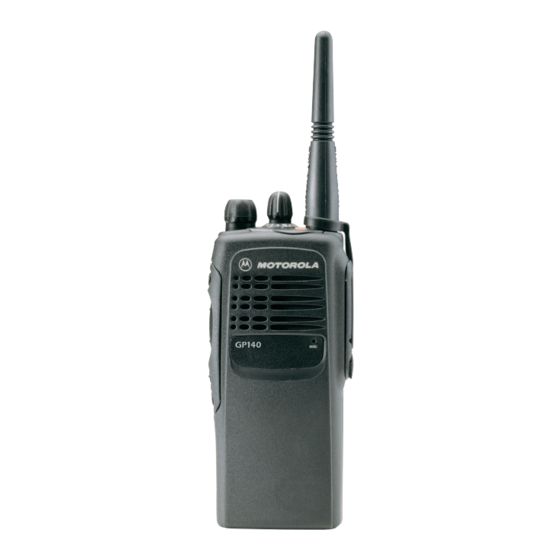
Motorola GP340 ATEX Service Information

Table of Contents

Chapter 1
1.0 GP340 Model Chart .............................................................................................1-1
2.0 GP640 / GP680 Model Chart ...............................................................................1-1
3.0 Technical Specifications ......................................................................................1-2
Chapter 2
1.0 Introduction ..........................................................................................................2-1
2.0 Transmitter...........................................................................................................2-1
2.1 Power Amplifier ..............................................................................................2-1
2.2 Antenna Switch...............................................................................................2-2
2.3 Harmonic Filter ...............................................................................................2-2
2.4 Antenna Matching Network ............................................................................2-2
2.5 Power Control Integrated Circuit (PCIC) ........................................................2-2
3.0 Receiver...............................................................................................................2-3
3.1 Receiver Front-End ........................................................................................2-3
3.2 Receiver Back-End.........................................................................................2-4
3.3 Automatic Gain Control Circuit .......................................................................2-5
4.0 Frequency Generation Circuitry ...........................................................................2-6
4.1 Synthesizer.....................................................................................................2-6
4.2 Voltage Controlled Oscillator (VCO)...............................................................2-8
Chapter 3
1.0 Troubleshooting Flow Chart for Receiver (Sheet 1 of 2)......................................3-1
2.0 Troubleshooting Flow Chart for Receiver (Sheet 2 of 2)......................................3-2
3.0 Troubleshooting Flow Chart for Transmitter ........................................................3-3
4.0 Troubleshooting Flow Chart for Synthesizer........................................................3-4
5.0 Troubleshooting Flow Chart for VCO...................................................................3-5
Chapter 4
PCB/SCHEMATICS/PARTS LISTS
1.0 Allocation of Schematics and Circuit Boards .......................................................4-1
1.1 Controller Circuits ...........................................................................................4-1
2.0 PCB 8485726Z01 - Schematics...........................................................................4-3
3.0 PCB 8485726Z01 - Parts List ............................................................................4-11
iii