Motorola Professional GP640 Service Information - Page 19

Browse online or download pdf Service Information for Radio Motorola Professional GP640. Motorola Professional GP640 30 pages. Professional radio, power distribution and controller
Also for Motorola Professional GP640: User Manual (32 pages), Specification Sheet (2 pages), Service Information (28 pages), Service Information (32 pages), Service Information (26 pages), Service Information (43 pages), Service Information (30 pages)
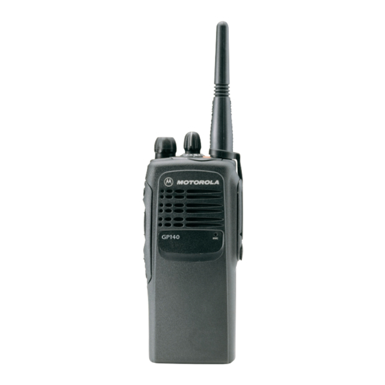
Motorola Professional GP640 Service Information
Frequency Generation Circuit
Tx
Rx
Battery Saver
In the receive mode, U3801 pin 19 is low or grounded. This activates the receive VCO by enabling
the receive oscillator and the receive buffer of U3801. The RF signal at U3801 pin 8 is routed
through a matching network. The resulting LO RF INJECTION signal is applied to the mixer at
T3302.
During the transmit condition, when PTT is pressed, 3.2 volts is applied to U3801 pin 19. This
activates the transmit VCO by enabling the transmit oscillator and the transmit buffer of U3801. The
RF signal at U3801 pin 10 is injected into the input of the PA module (U3501 pin16). This RF signal
is the TX RF INJECTION. Also in transmit mode, the audio signal to be frequency modulated onto
the carrier is received through U3701, pin 41.
When a high impedance is applied to U3801 pin19, the VCO is operating in battery saver mode. In
this case, both the receive and transmit oscillators as well as the receive, transmit and prescaler
buffer are turned off.
Table 2-1 Level Shifter Logic
Desired
AUX 4
Mode
n.u.
n.u.
n.u.
AUX 3
High (@3.2V)
High (@3.2V)
Low
Low
Hi-Z/Float
Hi-Z/Float (@1.6V)
(@1.6V)
TRB
2-9