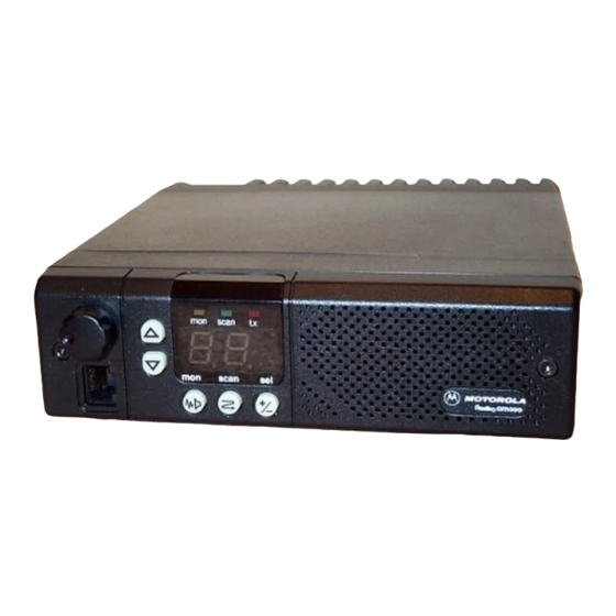
Motorola RADIUS GM300 Service Manual - Page 32
Browse online or download pdf Service Manual for Radio Motorola RADIUS GM300. Motorola RADIUS GM300 49 pages. 16-channel, conventional fm radio
Also for Motorola RADIUS GM300: Service Manual (28 pages), Operating Instructions Manual (18 pages), Operating Instructions Manual (19 pages), User Manual (37 pages), Operating Instructions (2 pages)

Name of Manual
off switch in this case. However, in 4-layer boards Q403
is a TMOS device, which exhibits very low on- resis-
tance (less than 0.6 ohm) and therefore negligible volt-
age drop, without requiring large base current ßow to
saturate it.
The 9.6V regulator uses an opamp as a controlling ele-
ment. The regulated output voltage is divided by R404
and R405 and compared with an accurate reference
voltage (5.03V DC) determined by VR401. The
opampÕs output voltage (U401A-1) varies the amount
of conduction in in Q402 and Q401 as necessary to keep
these two voltages (U401A-2 and -3) equal. A charac-
teristic of the opamp which allows the regulator to start
up is the fact that the output is high when both inputs
are low, which occurs momentarily at turn-on. Diode
CR401 is used to protect Q401 if the 9.6V line is
grounded. When this happens, Q402Õs base can only be
0.7V DC and Q401 will be turned off. Diode CR402 pro-
vides temperature compensation of the regulated out-
put voltage. The 9.6V supply powers the opamps in the
receive and transmit audio circuits, the D/A converter,
the RF board circuitry, and low level stages of the RF
power ampliÞer.
The 4.8V DC reference is formed by divider R408-R409,
Þltered by C405, and buffered by unity gain opamp
U401B to provide a low- impedance and low noise
half-supply reference voltage for the opamps in the
audio circuits.
The 5V regulator uses an IC, U402, to provide operat-
ing voltage for the microcomputer and logic circuits
and the front panel LED displays. This IC generates a
low reset pulse when turned on which is used to initial-
ize the microcomputer at power-up. The timing of this
pulse is determined by C409.
Microcomputer and Logic
GM300 radios use the Motorola 68HC11E9 microcom-
puter, U802, which utilizes:
¥ 7.776 MHz clock rate
¥ Multiplexed 8 bit address/data lines
¥ 16 bit addressing
¥ Internal watchdog circuitry
¥ Analog to digital conversion input ports
Additional control logic surrounding U802 consists of:
1. D/A CONVERTER U801. This IC is used to
generate precision analog voltages for trans-
mitter power control, deviation adjustment,
and reference oscillator frequency warp.
2. CUSTOM GATE ARRAY U803. This device
expands the input/output capabilities of the
control logic. U802 and U803 exchange infor-
March, 1997
mation which tells the microcomputer the
input port status and the desired state of the
output ports. Used in expanded logic boards
only.
3.
EPROM U804. This is an Erasable Program-
mable Read Only Memory, whose function is
to store the microcomputerÕs operating pro-
gram. Used in expanded logic boards only.
4.
EEPROM U805. This is an Erasable Program-
mable Read Only Memory, which acts as the
radioÕs code plug. It supplements the capabil-
ity of the EEPROM contained within U802,
storing additional operating information per-
tinent to a particular radio, such as operating
frequencies, signaling codes, scan lists, time-
out timer, programmable I/O assignments,
and other special functions. Used in expanded
logic boards only.
5.
SRAM U806. This Static Random Access
Memory is used for Òscratch padÓ operations.
Used in expanded logic boards only.
In masked logic boards, the microcomputerÕs operat-
ing program is permanently written or ÒmaskedÓ
within the microcomputer. Included in U802 is an
EEPROM memory which stores channel, signaling,
and scan list information, similar in function to U805
but with less storage capability.
Microcomputer Start-Up Routine
The microcomputer is operational after the RESET line
is released by U402 at turn-on. Y801, the crystal oscilla-
tor, should be stable at this point. Y801Õs frequency is
divided by four by U802 to produce the E-CLOCK
(1.944 MHz, at U802-5) which is the data clock for
microcomputer and, in expanded logic boards, gate
array U803. The microcomputer then executes a self-
test routine and generates an error tone if a failure is
detected. Q807 shifts the crystal frequency very
slightly by introducing network L801/C831 when
Q807 is off. This can be used to remove an on-channel
self-quieting signal which is a harmonic of the crystal,
if necessary.
Microcomputer Operation-Expanded Logic
In expanded logic boards, a successful self test of the
control logic will activate the multiplexed address/
data bus. The microcomputer has an eight bit address/
data bus and an eight bit address-only bus. These bus
lines are connected to gate array U803 for I/O port
information, and to the external memory ICÕs to send
and receive information.
The custom gate array must de-multiplex the lower
order address byte from the address/data bus (AD0-
AD7) in order to address a particular function or mem-
ory location.
68 No.
Theory of Operation
Logic Board
2-7
