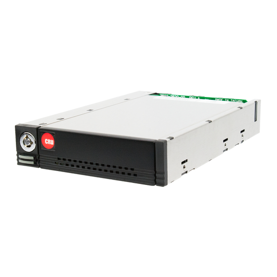
CRU DataPort DP25 SATA 6G Quick Start Manual - Page 2
Browse online or download pdf Quick Start Manual for Enclosure CRU DataPort DP25 SATA 6G. CRU DataPort DP25 SATA 6G 4 pages.

2
DataPort DP25 SATA 6G Quick Start Guide
1 General Information
1.1 Identifying Parts
Keylock
Eject Button
1.2 LED Behavior
LED
Drive Power
Drive Activity
2 Installation Steps
2.1 Frame Installation
a.
Slide the receiving frame into an open 3.5-inch bay in your computer and secure it to to the
chassis using the mounting screws provided.
b.
Attach a SATA data cable to the JP4 connector on the rear of the frame and attach the other end
to the appropriate SATA host. JP4 connects to the bottom drive in the carrier.
c.
If you plan to use a second drive, attach a SATA data cable to the JP5 connector on the rear of
the frame and attach the other end to the appropriate SATA host. JP5 connects to the top drive
in the carrier.
d.
Attach a 4-pin floppy power connector to the rear of the receiving frame. The frame requires both
+12VDC and +5VDC to operate. Most floppy connectors fulfill this requirement.
2.2 Drive Installation
a.
If a carrier is bundled with the frame, press the eject button once to release the button, and again
to eject the carrier from the frame. If the lock is engaged and the eject button will not release the
carrier, insert the provided Dataport Key into the frame and turn it 90 degrees counterclockwise
to release the lock so that you can eject the carrier.
Front
Two-Drive SATA Carrier
Color
STATE
Green
Solid
Amber
Blinking
SATA Data Connector
(Bottom Drive, Port JP5)
The drive inside the bay is powered on.
The drive inside the bay is being accessed by your computer.
Rear
SATA Data Connector
(Top Drive, Port JP4)
Power Connector
Description
