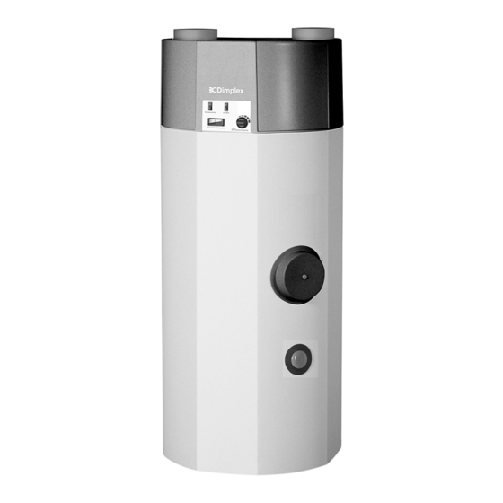
Dimplex KWP 300 Installation And Operating Manual - Page 15
Browse online or download pdf Installation And Operating Manual for Heat Pump Dimplex KWP 300. Dimplex KWP 300 17 pages. Dimplex kwp 300 heat pump for cooling of domestic water

11.3
Circuit Diagram
Legende
B1
Betriebsthermostat W P
B1 Operating thermostat, heat pump
B3
Regelthermostat-El.Heizung
B3 Regulating thermostat, el. heating
C1
Anlaufkondensator-Verdichter
C1 Starting capacitor, compressor
C2
Betriebskondensator-Ventilator
C2 Operating capacitor, fan
E1
El.Heizstab
E1 El. immersion heater
F1
HD-Pressostat
F1 HP pressostat
F2
Sicherheitsbegrenzer-Thermostat
F2 Safety limiter thermostat, el. heating
El.Heizung
F3 Klixon, compressor
F3
Klixon-Verdichter
K2 Starting relay, compressor
K2
Anlaufrelais-Verdichter
K3 All-or-nothing relay, HP pressostat
K3
Schaltrelais HD-Pressostat
M1 Compressor
M1
Verdichter
M2 Fan
M2
Ventilator
S1 "ON/OFF" switch, heat pump
S1
Schalter "EIN/AUS" W ärmepumpe
S2 "ON/Off" switch, el. heating
S2
Schalter "EIN/AUS" El.Heizung
X1 Mains plug
X1
Netzstecker
X3 Terminal strip, internal
X3
Klemmleiste intern
X3
L
N
PE
X1
L/N/PE 230VAC 50Hz
W ärmepumpe
Heat pump
Fan
Ventilator
Compressor
Verdichter
11
K3
14
black
schwarz
F3
C
P
M
X3-3
grün/gelb
green/yello
1
A
M1
M2
M
1
C2
X3-2
X3-1
B1
T >
2
+18..+26°C
1
S1
2
10
C1
21bar
(bn)
1
F1
P >
K2
2
L
PE
N
(bl)
14
A1
K3
A2
Elektro - Heizstab
el. Immersion heater
1
1
S2
4
2
31
K3
32
(+30 - +85°C )
+65°C
11
TR
B3/
T >
STB
F2
+99°C
12
E1
22
21
