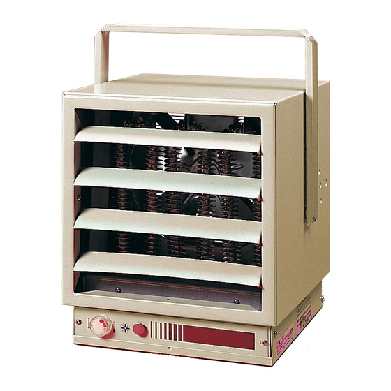
Dimplex EUH03B51CT Quick Manual
Browse online or download pdf Quick Manual for Electric Heater Dimplex EUH03B51CT. Dimplex EUH03B51CT 5 pages. Electric unit heaters

ELECTRIC UNIT HEATERS
MODEL EUH-B
Installation/ Start-up/ Maintenance
FOR HORIZONTAL OR VERTICAL AIRFLOW
PERMANENT OR SUPPLEMENTARY ELECTRIC FORCED AIR HEATING FROM THE SAME
VERSATILE UNIT
These heavy-duty heaters provide spot heating for hard to heat areas, or they can be used as the
primary
source of heat for areas not reached by an existing heating system.
The fan and motor are carefully matched to insure quiet, trouble-free operation and fan blades are precision
balanced before installation.
Heaters in all capacities (3, 5, 7-1/2, 10 or 12kw) have the same dimensions, and use the same mounting
brackets. All components and controls, including thermostat, transformers, relays, and switches are
enclosed inside the case. Wiring is simple and all heaters can operate from a single power source.
1. HEATER LOCATION: Unit heaters should be located along outside walls to provide perimeter air
circulation. The discharge air should wipe the walls without blowing directly on them. (Figure 1)
a. Small rooms - can be heated by one or two units. Locate the unit heater(s) to provide circular air
movement within the space.
b. Large rooms - requiring multiple unit installations. Units should be located so that the discharge air from
one unit supports the discharge from another unit and provides a circular air movement.
c. Remote thermostats - should be located on interior walls or posts away from heat sources, cold drafts,
and away from heater discharge streams.
2. MOUNTING UNIT HEATER(S): Heater should be mounted a minimum of ten (10) inches from walls
and six (6) feet above fl oor (8 feet for vertical air fl ow) with the discharge parallel to or away from wall.
(See Table A for recommended mounting heights)
a. MOUNTING BRACKET - The heater is shipped with a mounting bracket packed separately in the carton.
Secure the bracket to threaded attachment points on the sides of the heater with two bolts (provided).
Select desired angle of tilt (Horizontal, 15, 30, 45, 60, 75, or Vertical), remove corresponding knockouts
on sides of the heater, then screw the remaining two bolts into the threaded holes in the bracket so that
the bolts pass through the knockout holes. The unit is now ready for hanging.
b. CEILING MOUNTING - Fasten the heater securely to the ceiling using the center hole in the bracket
or the two holes on either side of the center hole. The Unit mounting bracket may be attached directly to
the ceiling.
c.WALL MOUNTING - The heater may also be mounted to a wall with accessory wall bracket,
(Part # EUHWB). The wall bracket attaches to the center hole of the unit mounting bracket.
EXPOSED OUTSIDE WALL
EXPOSED OUTSIDE WALL
SMALL ROOM
LARGE ROOM
FIGURE 1
7202450001R05
1-888-346-7539
