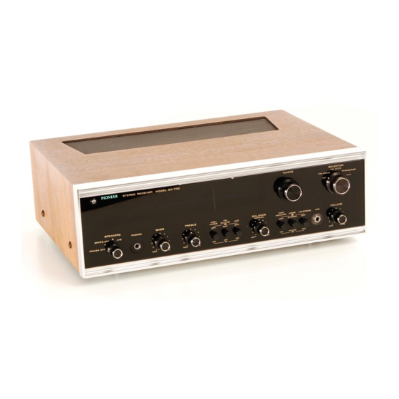
Pioneer SX-770 Installation, Operating And Service Manual - Page 17
Browse online or download pdf Installation, Operating And Service Manual for Receiver Pioneer SX-770. Pioneer SX-770 25 pages. Solid state am-fm stereo receiver

NPIONEE.R
PARTS
LIST
Symbol
Description
Part No.
c1
c2
c9
c10
cl1
c12
cl4
c15
c16
c17
c19
c20
c21
Ceramic
Ceramic
Mylar
Ceramic
Ceramic
E
lectrolytic
Ceramic
E
lectro
lytic
Oil
paper
Ceramic
Mylar
Mylar
E
lectrolytic
47P
47P
0.003
220P
220P
220
0.04
3000
0.01
0.01
0.0018
0.0018
4.7
+80%
-20%
50v
50v
50v
50v
50v
3V
50v
50v
D.C
1.4KV
50v
50v
16V
CCDSL4TOK5O
ccDSL470K50
coMA302K50
ccDSL221 K50
ccDSL221 K50
CETG22OMF3V
cKDYZ403K50
c52-066-0
c15-001-0
c43-003-o
coMA182K50
coMA182K50
CETG4R7MFl6V
POTENTIOMETERS
cApAc
r
ro R,
llf+r.,"t
*
l?
h:,?"*..
u
N
LEss
orH
E
RWrsE
RESISTORS
].ry-q,
1O%
TOLERANCE.
I/4
WATT
UNLESS OTHER-
o
FM
FRONTEND
(W11-035)
CAPACITORS
Ceramic
Ceramic
Ceramic
Cerarnic
15P
100P
3P
o-o2
50v
50v
50v
50v
Yr
c1
c2
c3
c4
ccDs
L1
50Ks0
CCDSLlOl
KsO
ccDsL030cso
0KDYZ203Z50
Symbol
Description
Part No.
VR1
VR2
2SOkSldual,
Volume
50kSldual,
Balance
c82-038-0
c85-052-0
WISE
NOTED k
:
kSZ,
M
MS,,
W
:
WATT
Symbol
Description
Part No.
R1
R2
B3
R4
R5
R6
R7\
R8\
Re/
R10/
R11
R12
R15
R16
R17
R18
R19
R20
R21
R22
R23
R24
R25
R27
Carbon
film
Carbon
film
Carbon
film
Carbon
film
Carbon
film
Carbon
film
Compound
part
for
REC.termina
Carbon
film
Carbon
film
Carbon
film
Carbon
film
Carbon
film
Carbon
film
Carbon
film
Carbon
film
Carbon
film
Carbon
film
Carbon
film
Carbon
film
Carbon
film
Carbon
film
1M
1M
100K
100K
68K
68K
33K
33K
3.9K
3.9K
1K
1K
39K
39K
150
150
1K
1M
100
2.2M
%v{
%w
%w
%w
%w
%w
3W
3A'
%w
%w
RFTaPS
1M-K
RF%PS
1M-K
RF'I4PS
lOOK-K
R
F']/.PS
1
OOK-K
RF'/4PS
68K-K
RF%PS
68K-K
w52-004-0
RF14PS
33K-K
RF%PS
33K-K
RF%PS
3R9K-K
RF%PS
3R9K.K
RF%PS
1K-K
RF%PS
1K.K
RF%PS
39K-K
RF%PS
39K-K
RO3P 150-K
RO3P 150-K
RF%PS
1K-K
RFy4PS
1M-K
RFy4PS lOO-K
RF/2PS
2R2M.K
MISCELLANEOUS
Symbol
Description
Part No.
FM FRONT
END
TUNER
Unit
MPX
Unit
HEAD
AMP
Unit
CONTROL
AMP
Unit
MAIN AMP
Unit
PUSH
SWITCH
Unit
(A)
PUSH
SWITCH
UNit
(B}
POWER
SUPPLY
Unit
MUTING
Unit
Front
Panel
Plastics Panel
Wooden
Base
Dial Pulley
Dial Pulley (for Tuning
Capacitor)
Dial
Glass
Dial Pointer
Knob, Selector
Knob,
Tuning
Knob, Volume,
Balance.
Bass
Treble"
Output
Selector
Tuning
Meter
Pilot
Lamp
(for
Dial
Glass)
Pilot
Lamp (for Tuning
Meter)
Pilot
Lamp
(for
FM Stereo)
Pilot
Lamp Socket
Bracket
for
FM Stereo
Fuse
2A
Fuse
Holder
Microphone
Jack
Headphone
Jack
Connector
5P
Jack
for
Speaker
Spare
AC
Outlet
Terminal
6P
Terminal
4P
Terminal
2P
Terminal
1P
wl
1-035-0
w35-012-B
w13-024-D
w1s-032-B
w15-033-0
w15-085-0
w15-086-0
w15-0874
w16-024-0
w18-026-0
M21-303{
M21-309-4
M52-112-O
M49-009-B
M42-O41-C
A33088-B
A31-087-A
A12-136-4
A12-139-A
412-131-A
A91-009-A
E22-O17-O
E22420-O
E22415-A
K42-003-0
A62-045-0
E21-O27-O
K96-007-0
K72-O20-O
K72-O21-B
K93{03-B
K73-003-A
K82-011-0
K22-O13-C
K22-O10-A
K2't-009-c
K21-0os-c
COILS
AND
TRANSFORMERS
Symbol
Description
Part No.
L1
L2
T1
AM
Ferrite Loopstick
Antenna
Choke Coil
POWER
Transformer
T42-O25-O
T24-030-0
T52-1 60-C
SWITCHES
Symbol
Description
Part No.
S1
s2
I
nput Selector
Output Seleitor
s13-030-0
s11-022-4
+o.25P
+80%
20%
l*
