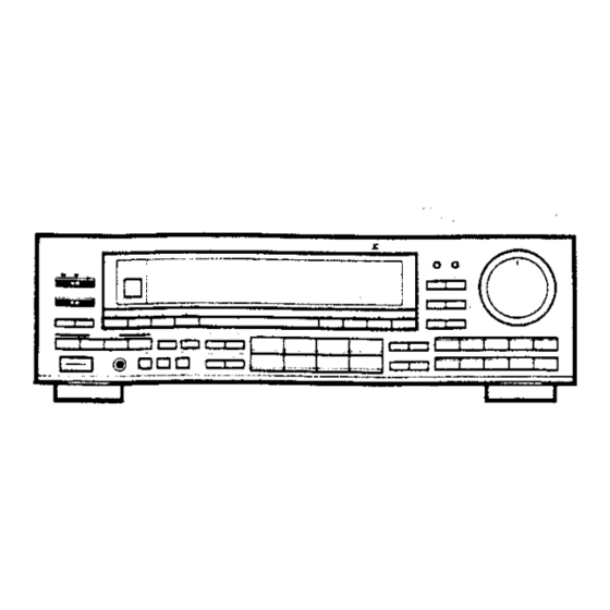
Pioneer VSX-5400 Operating Instructions Manual - Page 16
Browse online or download pdf Operating Instructions Manual for Stereo Receiver Pioneer VSX-5400. Pioneer VSX-5400 47 pages. Audio/video stereo receiver
Also for Pioneer VSX-5400: Service Manual (37 pages)

FRONT PANEL FACILITIES
@
POWER STANDBY/ON switch
e When the power cord is connected to a wall socket, the power will
remain on even when the POWER switch is turned off. The unit is
in the standby mode.
® When nothing is displayed in the display section, it is in the STANDBY
mode.
® The accessory remote control unit can also be used to turn the receiver
an or standby (STANDBY function).
* When not using the unit for a long period, disconnect the power cord.
NOTE:
When the power is initially turned ON, muting will be applied to prevent
sound from being output for about 5 seconds.
(@
VCR NOISE FILTER switch
If tape hiss is noticeable while performing playback of video cassette
tapes, press this switch to reduce the noise.
After pressing this switch, "VCR NOISE FILTER" will appear on the
display section.
NOTE:
* This switch can be used when either VCR 1 or VCR 2 function switch
is selected.
* The effectiveness in reducing high-frequency
hiss noise varies
depending on the type of tape used, the recording level, and other
conditions,
@® TV ANT (VIDEO/TV)
selector switch
This switch can be used in piace of the TV ANT switch on the RF
Modulator JA-RF5 (sold separately}. This is effective only when the
JA-RF5's TV ANT switch is set to the VIDEO position. For example:
In VIDEO mode (TV-ANT indicator in the display section goes off):
Allows you to use video components connected to the receiver.
in TV mode (TV-ANT indicator in the display section lights):
Connects the TV antenna, thus allowing you to view normal TV
broadcasts,regardless of whether the receiver's POWER is ON or OFF
{STANDBY},
NOTE:
* When in the VIDEO mode, no sound will be produced from the TV
set's speakers. Listen using the speakers connected to the receiver.
* Noise may be produced if the TV set's volume control is turned up.
Turn down the set's volume control when listening.
* This switch functions only when the TV ANT selector switch on the
RF Modulator is set to "VIDEO. *"
(@ Remote sensor
() SIMULATED STEREO switch
Press to preduce a simulated stereo effect when listening to monaural
sources (for example, normal AM or TV broadcasts).
"SIMULATED STEREO" appears on the display section.
NOTE:
This effect is net produced through the surround rear speakers.
©
ACOUSTIC switch
MEMORY:
:
Pressing this switch will result in the memorization of the sound quality
{tone control condition). Press again to cancel this mode.
SELECT:
* This switch is used to preset the five acoustic memories (A~E).
* This switch is also used to recail previously set sound quality settings.
Each time you press the switch, the sound quality setting advances
in the order shown below.
18
<ARB1174—>>
Ca
eee
eA
eB eC DE
1
FLAT: For flat (norma!) frequency response.
LOUDNESS:
Emphasizes the low- and high: frequency ranges. Produces a fuller
sense of sound, particularly when listening at low volume
A—E: Memorized acoustic memory settings.
[ Presetting the acoustic memory
@
Adjust the sound quality as desired using the BASS and TREBLE
control switches,
@ Settings are shown by the TONE indicator on the display section.
@ Press the ACOUSTIC MEMORY switch.
@ The TONE indicator on the display section blinks on and off.
®
Press the ACOUSTIC
SELECT
switch and select the acoustic
mernory to which you wish to assign the setting (A ~-
&).
® The sound quality setting is memorized
approximately two
seconds after you last press the ACOUSTIC SELECT switch.
In this way, the desired tone will be preset in ane of the five acoustic
memory positions, To preset four other desired tone settings, perform
the same operations.
To recall the memorized tone settings, press the ACOUSTIC SELECT
switch to select the desired memory position. in this way, five different
tone settings can be preset and recalled in the five positions of the
acoustic memory.
@ STATION NAME switch
This switch is used when
inputting station names
(see page 22,
"DISPLAYING STATION NAMES').
Press again to cancel this mode.
AUTO/MANUAL TUNING selector switch
This switch is used to select the tuning mode. The TUNING AUTO
indicator lights when the AUTO tuning mode has been selected. The
TUNING MANUAL indicator lights when the MANUAL tuning mode has
been selected (see page 19).
AUTO tuning
When the — or + TUNING switch is pressed, the receiver automatically
scans the broadcast station frequencies. When a broadcast is detected,
the scanning stops at that frequency.
NOTE:
Pressing the TUNING switch (~ or +} while scanning is taking place
causes scanning to stap.
MANUAL tuning
This lets you manually tune to particular broadcast frequencies. Each
press of the + or ~ switch raises or lowers the frequency by one tuning
step. For continuous scanning, keep the switch depressed, then release
it to stop scanning.
@
DIRECT ACCESS TUNING switch
When this switch is pressed, the STATION CALL switches function as
ten-key number switches for direct input of the desired reception
frequency. Press again to cancel this mode.
If the input station falis outside of the receiver's tuning range, the display
section will display a message: ''UPPER" if the frequency is too high
and LOWER" if it is too low.
