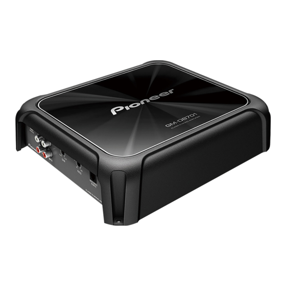
Pioneer GM-DX971 Owner's Manual - Page 12
Browse online or download pdf Owner's Manual for Amplifier Pioneer GM-DX971. Pioneer GM-DX971 16 pages. Class d mono amplifier
Also for Pioneer GM-DX971: Owner's Manual (16 pages)

- 1. About this Product
- 2. Before Connecting/ Installing the Amplifier
- 3. Setting Gain Properly
- 4. Connection Diagram
- 5. Before Connecting the Amplifier
- 6. Connecting the Speakers
- 7. Connections When Using the Speaker Input Wire
- 8. Solderless Terminal Connections
- 9. Connecting the Speaker Output Terminals
- 10. Before Installing the Amplifier
- 11. Attaching the Bass Boost Remote Control
- 12. Example of Installation on the Floor Mat or Chassis
- 13. Specifications
(_l_ns_t_a_lla_t_io_n _ _ _ _ _ )
Attaching the Bass boost
remote control
Attach with tapping screws (3 mm x 1 O mm
(1/8 in. x 3/8 in.)) at an easily accessible loca-
tion such as under the dashboard.
I
A
L,J
Tapping screws (3 mm x 10 mm (1/8 in. x 3/
8 in.))
Example of installation on
the floor mat or chassis
1
Place the amplifier in the desired instal-
lation location.
Insert the supplied tapping screws (4 mm x
18 mm (5/32 in. x 3/4 in.)) into the screw holes
and push on the screws with a screwdriver so
they make an imprint where the installation
holes are to be located.
2
Drill 2.5 mm (3/32 in.) diameter holes at
the imprints either on the carpet or directly
on the chassis.
En
(
______
)
3
Install the amplifier with the use of
supplied tapping screws (4 mm
x
18 mm
(5/32 in. x 3/4 in.)).
G)
Tapping-screws (4 mm x 18 mm (5/32 in. x
3/4 in.))
®
Drill a 2.5 mm (3/32 in.) diameter hole.
®
Floor mat or chassis
®
Hole-to-hole distance: 229.5 mm (9-1/32 in.)
(GM-D8701 and GM-DX871) / 279.5 mm
(11 in.) (GM-D9701 and GM-DX971)
®
Hole-to-hole distance: 191.5 mm
(7-17/32 in.)C!l
