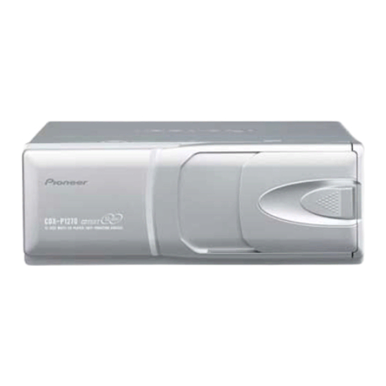
Pioneer CDX-P1270 Service Repair Training - Page 31
Browse online or download pdf Service Repair Training for CD Player Pioneer CDX-P1270. Pioneer CDX-P1270 50 pages. Multi-compact disc player
Also for Pioneer CDX-P1270: Owner's Manual (4 pages), Owner's Manual (4 pages), Owner's Manual (4 pages), Owner's Manual (18 pages)

- 1. Table of Contents
- 1. 1 Safety Information
- 2. 2 Exploded Views and Parts List
- 3. 3 Block Diagram and Schematic Diagram
- 3. CD Mechanism Module
- 4. 4 Pcb Connection Diagram
- 5. 5 Electrical Parts List
- 6. 6 Adjustment
- 7. 7 General Information
- 7. Diagnosis
- 7. Test Mode
- 7. Disassembly
- 7. Connector Function Description46
- 7. Operational Flow Chart
- 8. 8 Operations and Specifications
6. ADJUSTMENT
6.1 CD ADJUSTMENT
- Precautions
• This unit uses a single power supply (+5V) for the reg-
ulator. The signal reference potential, therefore, is
connected to REFO(approx. 2.5V) instead of GND.
If REFO and GND are connected to each other by mis-
take during adjustments, not only will it be impossi-
ble to measure the potential correctly, but the servo
will malfunction and a severe shock will be applied to
the pick-up. To avoid this, take special note of the fol-
lowing.
Do not connect the negative probe of the measuring
equipment to REFO and GND together. It is especially
important not to connect the channel 1 negative
probe of the oscilloscope to REFO with the channel 2
negative probe connected to GND.
Since the frame of the measuring instrument is usual-
ly at the same potential as the negative probe, change
the frame of the measuring instrument to floating sta-
tus.
If by accident REFO comes in contact with GND,
immediately switch the regulator or power OFF.
• Always make sure the regulator is OFF when connect-
ing and disconnecting the various filters and wiring
required for measurements.
• Before proceeding to further adjustments and mea-
surements after switching regulator ON, let the player
run for about one minute to allow the circuits to stabi-
lize.
• Since the protective systems in the unit's software are
rendered inoperative in test mode, be very careful to
avoid mechanical and /or electrical shocks to the sys-
tem when making adjustment.
• Disc detection during tray extraction and return oper-
ations is performed by means of the photo transistor
in this unit. Consequently, if the inside of the unit is
exposed to a strong light source with the outer casing
removed for repairs or adjustment, the following mal-
functions may occur:
*Even with a disc loaded, the unit detects "no disc"
and cannot start play.
*Although a 12-cm disc is loaded, the unit detects
"8cm disc" mistakenly.
When the unit malfunctions this way, either re-posi-
tion the light source, move the unit or cover the photo
transistor.
• During exchanging discs, do not press the keys for
the discs to be exchanged.
Key to adjustment text
inside (12 keys type)
BAND
TRK+/FF
TRK-/REV
7
8
9
10
11
12
DISC-
SOURCE ON/OFF
CDX-P1270
HEAD UNIT (6 keys type)
BAND
TRK+/FF
TRK-/REV
1
2
3
4
5
6
DISC-
SOURCE ON/OFF
31
