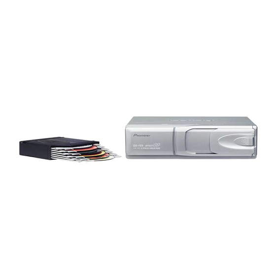
Pioneer CDX-P670 Service Manual - Page 48
Browse online or download pdf Service Manual for CD Player Pioneer CDX-P670. Pioneer CDX-P670 50 pages. Multi-compact disc player
Also for Pioneer CDX-P670: Owner's Manual (4 pages), Owner's Manual (4 pages), Service Manual (50 pages), Owner's Manual (4 pages), Owner's Manual (17 pages)

CDX-P670,P676
QQ
3 7 63 1515 0
Pin No.
Pin Name
65–68
A6-A3
69
A10
70
A2 & (EPSK)
71
A1 & (EPDI)
72
A0 & (EPDO)
asensfm
73
ejsw
74
mag
75
76
CDMUTE
77
NC
78
I13
79
I2
80
I4
81–88
D0-D7
89,90
NC
91
DSP
disk
92
93
ELVPVO
94
ELVREF
95
TRP
96
AVSS
97
VDIN
98
VREF
99
AVCC
100
EPCS
*PD5638A
TE
L 13942296513
80
81
100
1
LC35256FT-70U
A0-A14 : Address input
IO1-IO8 : Data input/output
CS: Chip select
www
.
48
http://www.xiaoyu163.com
I/O
Format
O
C
O
C
O
C
O/I
C
O
C
I
I
I
O
C
O
C
O
C
O
C
I/O
C
I
I
I
I/O
C
51
50
31
30
OE : Output enable
WE : Write enable
VDD : Power supply
GND : GND
x
ao
u163
y
i
http://www.xiaoyu163.com
2 9
8
Function and Operation
SRAM address bus output
SRAM address bus output
SRAM address bus output and (E2PROM clock output)
SRAM address bus output and (E2PROM data input)
SRAM address bus output and (E2PROM data output)
Pull up
Eject key switch interrupt input
Magazine lock switch interrupt input
CD mute output
Not used
Motor driver control output
Motor driver control output
Motor driver control output
SRAM data bus input/output
Not used
DISC detect timing input
Disc detector input
Voltage input from ELV position sense
ELV reference voltage input
Tray position input
A/D GND
Power supply short sensor input
A/D converter reference voltage input
A/D VCC
E2PROM detect input , Chip select output
Q Q
3
6 7
1 3
1 5
Format
C
IC's marked by* are MOS type.
Be careful in handling them because they are very
liable to be damaged by electrostatic induction.
TC7SH32F
1 IN B
2 IN A
3 GND
co
.
9 4
2 8
0 5
8
2 9
9 4
2 8
Meaning
C MOS
5 VCC
m
4 OUT Y
9 9
9 9
