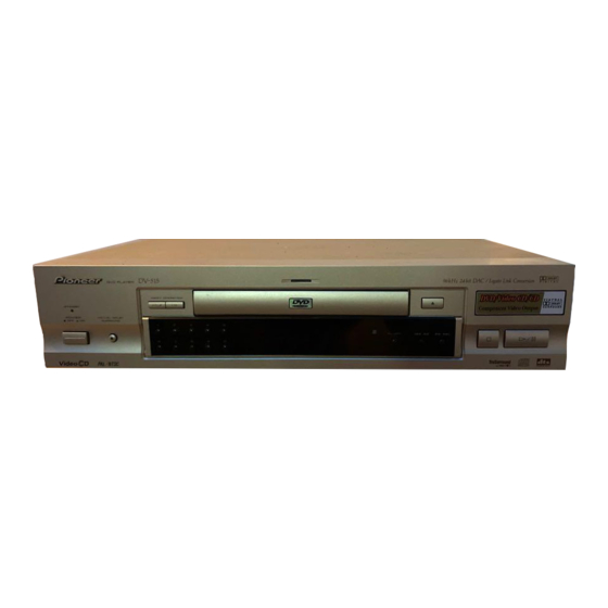
Pioneer DV-515 Service Manual - Page 14
Browse online or download pdf Service Manual for DVD Player Pioneer DV-515. Pioneer DV-515 26 pages.
Also for Pioneer DV-515: Service Manual (48 pages)

DV-515
(10) Output video system [V – ∗ ∗ ∗ ∗]
NTSC system
PAL system
Auto-setting
(11) FTS servo IC information
Indications for the following two types of information can be
switched:
1 DSP coefficient indication
Displays the address (four digits) of the specified coefficient
and the setting value (four digits) with [TEST] and [9] keys.
2 Jitter value indication
Displays the jitter value (four digits) with [TEST] and [DIG/
ANA] keys.
(12) Error rate indication
1 C1 error value of CD
2 C1 error value of DVD
(13) Internal operation mode of mechanism controller
[MM – ∗ ∗ : ∗ ∗]
Internal mechanism mode (2 digits) and internal mechanism step (2
digits) of the mechanism controller
Note : For details, see the specifications of the mechanism controller.
(14) 1 Disk sensing [DSC – ∗ ∗ ∗]
The type of discs loaded is displayed.
[DVD], [CD ], [CDV], [LD ], [VCD], [
2 CD 1/3 beam switch [BM – ∗ ∗]
(15) Pickup [PU – ∗ ∗ ∗]
The pickup being operating is displayed.
DVD
CLD
The wavelength 650 or 780 is displayed while executing LD on
(approx. 10 seconds) with the command.
DVD 650
[DVD 650 nm during LD on]
DVD 780
[DVD 780 nm during LD on]
(16) Version of the AV-1 chip [ AV1 = ' ∗ ' ]
Flash ROM size
(17) 1 Destination setting of the FL controller
[F : ∗ ∗ ∗ / ∗ ∗ ∗]
Three characters in front represent the type of model:
515 : DV-515,
H9 : DVL-H9,
05 : DV-05,
919 : DVL-919, 717 : DV-717
Three characters that follow represent the destination code.
J : /J, K: /KU, /KC, /KU/KC,
R: /RAM/RL/RD/LB, WY: /WY,
2 Region setting of the player [REG : ∗ ]
Setting value
14
[NTSC]
[PAL ]
[AUTO]
[KS – [∗ ∗ ∗ ∗] ∗ ∗ ∗ ∗ ]
[JT – [ 0 0 0 0 ] ∗ ∗ ∗ ∗ ]
[ER – C1 ∗ ∗ ∗ ∗ ]
[ER – ∗ ∗ ∗ ∗ ∗ ∗ ∗ ∗ ]
]
[DVD]
[CLD ]
[FLASH=∗]
414 : DV-414,
[1] to [6]
(18) Version of the flash ROM [V : ∗ . ∗ ∗ ∗ ]
(19) Revision of the system controller
[S : ∗ . ∗ ∗ ∗ / ∗ . ∗ ∗ ]
1 Revision number of the external ROM part (flash ROM) of the
system controller
2 Revision of the internal ROM part of the system controller
(20) Revision of the DVD mechanism controller
[M : ∗ . ∗ ∗ ∗ / ∗ . ∗ ∗ ∗ ]
1 Revision number of the external ROM part (flash ROM) of the
DVD mechanism controller
2 Revision of the internal ROM (core part) of the DVD mechanism
controller
(21) Revision of the CLD mechanism controller
[L : ∗ . ∗ ∗ ∗ ]
(22) Version of the AV-1 chip [AV : ∗ . ∗ ∗ ]
(23) Version of the FL controller [F : ∗ . ∗ ]
(24) Control and part numbers of the GUI-ROM
[GUI : ∗ ∗ ∗ / ∗ ∗ ∗ ∗ ]
1 Control number of the GUI-ROM (3-figure number of decimal)
2 Part number of the GUI-ROM
No GUI model displays as "––– / ––––".
(25) The part number of the flash ROM and system
controller [S : ∗ ∗ ∗ ∗ ∗ ∗ / ∗ ∗ ∗ ∗ ∗ ∗ ∗ ]
1 Part number of the flash ROM
(Example) VYW1536-A
(Example) PD6256A9
2 Part number of the system controller
(Example) PD3381T1
(26) Part number of the DVD mechanism controller
(Example) PD4889A0
(PE5012A0)
(27) Part number of the CLD mechanism controller
(Example) PD0260A2
(28) 5.1CH output mode indication (5.1/2)
(29), (30), (31) Speaker ON/OFF indication
<Front>
<Rear>
<Front>
<Rear>
<Front>
<Rear>
<Front>
= W1536A
= 6256A9
<Rear>
= 3381T1
= 4889A0
= 0260A2
