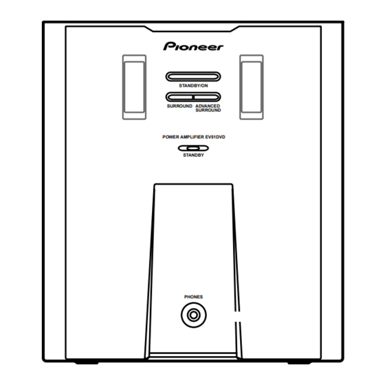
Pioneer M-EV51 Service Manual - Page 46
Browse online or download pdf Service Manual for Speaker System Pioneer M-EV51. Pioneer M-EV51 49 pages. Stereo power amplifier
Also for Pioneer M-EV51: Service Manual (49 pages)

1
7.1.3 SINGLE OPERATION METHOD
Single operation method and input level.
A
Note : Before the diagnosis, discharge the Amp power line. Connect the resistor of 100Ω or more between W301(VH+), W303(VH–) and
GND (CN3003 Pin1) on the E-VOL ASSY. Refer to the next page about the points.
The procedure and the input level of a single operation are shown below.
1. Short R84 with 1kΩ on the PRIMARY ASSY.
2. The power supply of the unit is turned on.
3. The terminal SPCONT(7 pin of CN3002) on the E-VOL ASSY is controlled by the following voltages.
The initial state is "SP Relay is OFF" and "Sys. Mute is ON". Apply DC+12V to SPCONT so that AMP can output to the speaker terminal.
[ SPCONT ]
SP Relay
B
Sys. Mute
[ The Signal Input ]
Note : This unit has the electric volume and this volume is only controled by U-com in the Receiver.
So, please input the signal to the point after the electric volume output.
Signal Input/Output Point
Input Point
FL ch
FR ch
SL ch
C
SR ch
C ch
SW ch
IC3009 3Pin
R84 1kΩ Point
G
PRIMARY ASSY
D
E
F
46
1
2
CONT
0V
5V
12V
OFF
ON
ON
ON
OFF
Output Point
Gain (1kHz)
R3101
Speaker Out
47 dB
R3102
Speaker Out
47 dB
R3111
Speaker Out
36 dB
R3112
Speaker Out
36 dB
R3121
Speaker Out
36 dB
PRE Out
0 dB (100Hz)
R84 1kΩ
Point
2
3
ON
Input Level(rms) Output Level(rms)
44.6 mV
44.6 mV
44.6 mV
44.6 mV
44.6 mV
Check that it is not
muted by Q3009.
SIDE A
W132
H6
NDING
W141
9
FU3
8
PT NK
W132 W111
MY/NV/NK
WIRE
ALL
C5
SECONDARY
SIDE
M-EV51
3
4
10 V
10 V
2.8 V
2.8 V
2.8 V
H5
TX WINDING
CHK
W133
C1
/YPW
C3
JP
W147
L1
W146
TUBE SIDE
D88
RY81
D92
Q81
D93
R91
C84
Q83
R84
C81
AMP
POW ON
C83
W145
IC1
W155
78M56
I
O
W139
V+12UN
D84
PRINTED
1
D96
SIDE
C82
1.POWER
ON/OFF
1
2.GNDD
3.UN5.6
4.AC
C75
OPEN SIDE
4
CN6
C91
4
CN7
4
