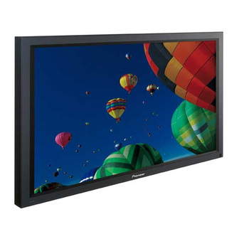
Pioneer Elite PRO-1000HDI Operating Instructions Manual - Page 42
Browse online or download pdf Operating Instructions Manual for Monitor Pioneer Elite PRO-1000HDI. Pioneer Elite PRO-1000HDI 48 pages. Pioneer 3rd, 4th % 5th generations plasma panel quick reference parts lists
Also for Pioneer Elite PRO-1000HDI: Quick Reference Parts Lists (12 pages)

Additional Information
Specifications
General (PRO-1000HD
I
)
Light emission panel ............ 50 inch plasma display panel
Number of pixels .............................................. 1280 x 768
Power supply ........................................... AC 120 V, 60 Hz
Rated current ............................................................. 3.2 A
Standby power consumption ...................................... 1 W
External dimensions ... 1259 (W) x 776 (H) x 104.7 (D) mm
............................. 49-9/16 (W) x 30-9/16 (H) x 4-1/8 (D) in.
Weight ............................................. 46.5 kg (102 lbs. 8 oz)
General (PRO-800HD
I
)
Light emission panel ............ 43 inch plasma display panel
Number of pixels .............................................. 1024 x 768
Power supply ........................................... AC 120 V, 60 Hz
Rated current ............................................................. 2.5 A
Standby power consumption ................................... 0.9 W
External dimensions ...... 1111 (W) x 692 (H) x 104 (D) mm
....................................... 43-3/4 (W) x 27-1/4 (H) x 4 (D) in.
Weight ............................................. 38.5 kg (84 lbs. 11 oz)
Input/output
Video
INPUT 1
Input
Mini D-sub 15 pin (socket connector)
1 RGB signal (G ON SYNC compatible)
RGB ... 0.7 Vp-p/75 /no sync.
HD/CS, VD ... TTL level
/positive and negative polarity
/2.2 k
G ON SYNC
... 1 Vp-p/75
*Compatible with Microsoft's Plug & Play
(VESA DDC1/2B)
2 Component video signal
Y ... 1 Vp-p/75 /negative sync.
C
/P
, C
/P
B
B
R
R
... 0.525 Vp-p/75
(75% satulation level)
Output Mini D-sub 15 pin (socket connector)
75 /with buffer
INPUT 2
Input
BNC jack (x5)
1 RGB signal (G ON SYNC compatible)
RGB ... 0.7 Vp-p/75 /no sync.
HD/CS, VD ... TTL level
/positive and negative polarity/
75
or 2.2 k
(impedance switch)
G ON SYNC ...
1 Vp-p/75 /negative sync.
38
I
I
PRO-1000HD
/ PRO-800HD
/negative sync.
2 Component video signal
Y ... 1 Vp-p/75 /negative sync.
C
/P
, C
/P
B
B
R
R
... 0.525 Vp-p/75
(75% satulation level)
INPUT 3
Input
S terminal (Mini DIN 4 pin)
• Y/C saparate video signal (NTSC)
Y . . . 1 Vp-p/75 /negative sync.
C . . . 0.286 Vp-p/75
INPUT 4
Input
BNC jack
• Composite video signal (NTSC)
1 Vp-p/75 /negative sync.
INPUT 5
Input
HDMI jack
• Digital signal
3.3 V T.M.D.S. / 50
Audio
Input
AUDIO INPUT (for INPUT 1/2)
Stereo mini jack
L/R ... 500mVrms/more than 10 k
AUDIO INPUT (for INPUT 3)
Pin jack (x2)
L/R ... 500mVrms/more than 10 k
AUDIO INPUT (for INPUT 4)
Pin jack (x2)
L/R ... 500mVrms/more than 10 k
AUDIO INPUT (for INPUT 5)
Pin jack (x2)
L/R ... 500mVrms/more than 10 k
Output AUDIO OUTPUT
Stereo mini jack
L/R ... 500mVrms (max)/less than 5 k
SPEAKER
L/R ... 8 – 16 /2W +2W (at 8
Control
RS-232C ... D-sub 9 pin (pin connector)
COMBINATION IN/OUT
... Mini DIN 6 pin (x2)
CONTROL IN/OUT ... monaural mini jack (x2)
Accessories
Power cord ....................................................................... 1
Remote control unit ......................................................... 1
AA (R6) batteries .............................................................. 2
Cleaning cloth ................................................................... 1
Speed clamps ................................................................... 2
Bead bands ...................................................................... 2
Warranty ........................................................................... 1
Operating Instructions ...................................................... 1
÷ Due to improvements, specifications and design are subject to
change without notice.
)
