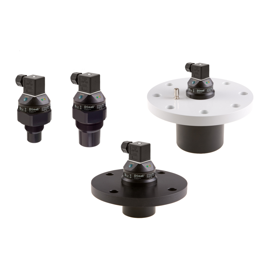
Dinel ULM-53 10 Manual - Page 4
Browse online or download pdf Manual for Laser Level Dinel ULM-53 10. Dinel ULM-53 10 6 pages. Ultrasonic level meters

I
NSTALLATION
Level meter is installed into the upper lid of the tank (vessel), using a fi xing nut or a fl ange.
If installed in an open channel (sumps, reservoirs, etc.), install the level meter as closest as you can to the maximum level
expected.
The front of the level meter must run in parallel to the measured level.
Emitted acoustic signal must not be affected by near objects (stiffeners, ladders, mixers, unevenness, etc.), stream of fi lling, air
fl ow, etc.
Foam on the level absorbs the acoustic wave refl ection which might cause malfunction of the level meter. If possible select the
location where the foaming is as low as possible.
Protect the level meter against direct sunlight.
In the case of uncertainty we recommend to consult the application with the producer.
M
OUNTING RECOMMENDATION
Recommended installation
Installation distance from the tank wall
c - measuring range
d - min. distance from tank wall
1 12
ULM–53–02; 10
(
. 200
min
mm
1 8
ULM–53–06
(
min
. 200
mm
1 10
ULM–53–20
(
. 200
min
mm
ULM–53–02; 06
ULM–53–10
ULM–53–20
a - neck height
b - neck width
m - dead zone
Possible installation through the neck
)
)
)
a
3
100
mm
1,5
a
100
mm
1,5
a
150
mm
m - dead zone
Maximum level distance from ULM
ULM-53-dat-4.6
