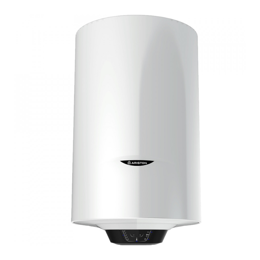
Ariston PRO1 ECO Series Manual - Page 12
Browse online or download pdf Manual for Water Heater Ariston PRO1 ECO Series. Ariston PRO1 ECO Series 19 pages. Unvented

COMMISSIONING
- Check that all the necessary components are supplied and for those not factory fitted, that they are the type recom-
mended by the manufacturer for the particular water heater.
- Check that the water heater/components are undamaged.
- Check that the discharge pipe is plumbed so that it falls continuously and that no taps, valves or other shut-off de-
vices are installed in the pipe.
- Check that the discharge pipe drains safely to waste and is readily visible.
- Check, in the case where some components are not factory fitted, that they are marked so as to refer to the warning
label on the water heater.
- Open all outlet taps.
- Turn on the mains water supply.
- Close taps in turn as water flow stabilises with no air bubbles.
- Check for leaks.
- Check that no water is passing through the safety valve(s).
- Test the operation of the safety valve(s) by lifting/turning the lever/knob, and observing that water flows through
and safely to waste.
- Switch on electricity and set thermostat to at 60°C to reduce the build up of scale in hard water areas.
- Check the water heats up.
- Check that <<warning to user label>> is secure and visible on the heater and related warning labels are fitted to the
controls.
- Demonstrate operation to user, including operation of safety valve(s) and what to do if it/they operate(s).
- Give this handbook to the user and discuss future maintenance.
- Drain and refill the entire system ensuring it is flushed in accordance with BS6700.
MAINTENANCE REGULATIONS (for qualified personnel)
Before calling your Technical Servicing Centre, check that the fault is not due to lack of water or power failure.
Caution: disconnect the appliance from the mains before conducting any maintenance work.
Replacing parts (Fig. 4)
Remove the enclosure to access the electrical equipment.
To work on the electronic thermostat (Ref. T), disconnect the power supply cable (Ref. C) and the control panel wire (Ref.
Y). Next, remove it from its slot, taking care not to bend the sensor support rod too much.
To work on the control panel (Ref. W), disconnect the wire (Ref. Y) and loosen the screws.
During reassembly, make sure that all components are put back in their original positions.
In order to work on the heating element and the anode, the appliance must first be emptied.
Undo the 5 bolts (C fig. 5) and remove the flange (F fig. 5). The heating element and anode are attached to the flange.
During reassembly, make sure that the flange gasket, the thermostat and the heating element are put back in their
original positions (Fig. 5).
We recommend replacing the flange gasket (Z Fig. 6) every time it is disassembled.
Use only original parts from authorised service centres authorised by the manufacturer.
Periodical maintenance
The heating element (R fig. 6) should be descaled every two years (the frequency must be increased, if water is very
hard) to ensure it works properly. If you do not wish to use a liquid descaler (in this case please read the safety data
sheets of descaling), you can simply break off the deposit, taking care not to damage the heating element's cladding.
The magnesium anode (N fig. 6) must be replaced every two years, otherwise the decay of the warranty. In the presence
of aggressive or waters rich in chloride it is recommended to check the status of the anode annually.
To remove this, disassemble the heating element and unscrew from the support bracket.
Check controls (where fitted) as per the following:
- Line strainer - with the water supply turned off remove screen from strainer and clean of any detritus;
- Expansion vessel - with the water supply turned off and taps open, check expansion vessel pressure and top up as
necessary;
- Temperature & pressure relief valve - with the water supply turned on, check manually by lifting the test lever/turn-
ing the test knob (ensure valve closes after testing);
- Expansion relief valve - check manually by turning the test knob (ensure valve closes after testing);
- Discharge pipes (D1) - from both temperature & pressure relief and expansion relief valve for obstructions;
- Tundish & discharge pipe (D2)- open either valve gradually to produce a full bore discharge into tundish and D2
without any back pressure;
- Pressure reducing valve - check that the correct outlet pressure is being maintained by recording the pressure at an
in-line terminal fitting i.e. tap.
