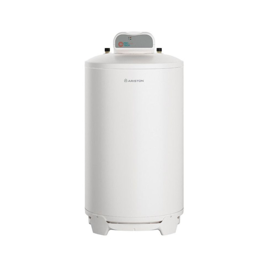
Ariston BCH 120 L Technical Installation Instructions And User Manual - Page 27
Browse online or download pdf Technical Installation Instructions And User Manual for Boiler Ariston BCH 120 L. Ariston BCH 120 L 29 pages. Heating tank

PROTECH
The PROFESSIONAL TECH system, an exclusive solution, is an electronic system which protects against corrosion and ensures the maximum life
of your water heating tank, even where water quality is poor.
The electronic circuit allows a di erence in potential to be created between the tank and the titanium electrode, in such a way as to guarantee
optimum protection of the tank and prevent corrosion.
Optimum functioning of the protection system REQUIRES A PERMANENT CONNECTION TO A 230V SUPPLY, even when the hot water generator
is not running. To be able to disconnect the protection system for longer than 2 hours without risking the length of the tank's useful life, it is
essential to drain the tank beforehand! !!
The electronic circuit is linked to the 230V network, and also to the tank being protected and the titanium protection electrode, as shown in
the diagram on the following page.
Correct functioning of the protection system is indicated by the green indicator light coming on, which shows that the circuit terminals are live.
In case of a fault, the red indicator light will signal that there is a short circuit between the electrode and the tank, that one of the cables (tank
or electrode) is detached, or that there is no water in the tank.
Therefore, your hot water generator is correctly protected if the green indicator light is on and the red light is o . If this is not the case, please
call your installer.
Note for the installer
Important: do not carry out any operation without having rst cut the electricity supply from the 230V network, (as this is a quick operation, it
can be carried out without rst draining the tank and not necessarily cause corrosion).
The electronic circuit can be replaced very easily, without draining the tank, by:
- Unplugging the two supply lines that lead from the electronic circuit to the supply terminal block,
- Unplugging the quick connector with polarising slot that links the circuit to the tank and the electrode,
- Detaching the electronic circuit from its support (plastic clips in the 4 corners),
- To replace a defective circuit with a new one, perform the above steps in reverse order.
Diagnosing electronic circuit failure
1) The GREEN light is not on :
-- Verify that the circuit supply line is plugged in (if not, plug it in),
- Check that the electronic circuit is being supplied (if not, replace the supply cable),
- Verify that the power being supplied is 230V (if not, supply 230V),
- If all the above have been veri ed and there is still a fault, replace the electronic circuit (installer).
2) The RED light is on :
- Verify that the tank is full of water (if not, ll it so that the following checks can be carried out),
- Verify that the quick connector is properly positioned (if not, correct this),
- Verify that the electrode connection cable (that enters the glove nger in the base) is properly connected (pull it
gently from above to make sure it is connected) (if not, replace the base and its electrode),
- Verify that the tank connection cable is properly connected to the tank (if not, connect it correctly),
- Verify that the two cables coming from the quick connector are not damaged or stripped, etc. (if they are, replace the base and
its electrode),
- If all the above have been veri ed and there is still a fault, replace the electronic circuit (installer).
Request the assistance of your installer.
Technical Installation Instructions and User Guide
GB
27
