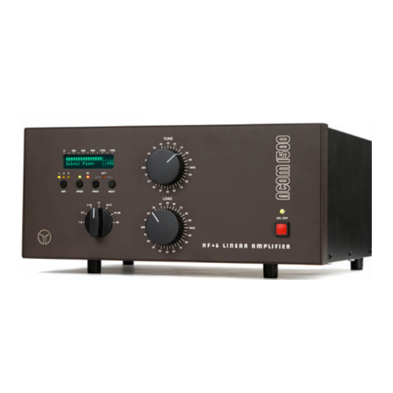
Acom 1500 Replacement Manual - Page 7
Browse online or download pdf Replacement Manual for Amplifier Acom 1500. Acom 1500 9 pages. Tube replacement

Select same bands (preferably lower) on both the amplifier and the exciter.
Use a small-size flat-tip insulated screwdriver for the next adjustments. Locate
the two trimmer potentiometers RP1 and RP2 (marked "BIAS1" and "BIAS2") on the
MAINS PCB. They control the idling (zero-signal) plate current of the tube for
low- and high- RF drive levels respectively.
Please note that RP2 will affect both levels, while RP1 - only the low level of
the idling current. That is why, the high level is adjusted the first, and only
then is set the low level (according to the procedure described below).
b) Select the "Plate Current" information screen on the LCD. Go to the OPER mode.
Apply very small drive power in CW mode key down (1-3W RF). Following the plate
current, adjust R2 (BIAS2) to 250mA (CCW rotation will increase the current and
vice versa). Don't exceed 15 seconds with the PTT on. If you need more time for
fine adjustment, make a pause of 1-2 minutes to let the tube cooling down and then
repeat the adjustment.
c) For RP1 (BIAS1) adjustment press the PTT but do not apply any RF drive. For
instance, select SSB mode with the exciter MIC and POWER regulators set to
minimum; in CW you may press the TX button but without closing the CW key.
While monitoring the plate current, adjust RP1 (BIAS1) to set the plate current to
70mA (flickering between 60 and 80mA is OK). A CW rotation of RP1 will increase
the current and vice versa. The adjustment of RP1 (BIAS1) does not affect the
previous step so you are ready.
7. Reassembling the Amplifier
After the adjustment procedure is completed, switch off the amplifier and pull the
amplifier power plug out of the mains wall outlet. Wait for a minimum five minutes
to expire and only then remove both "cover-presence" imitators. Do not hurry to
7
