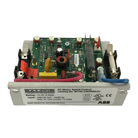
ABB Baldor BC142-5 Installation & Operating Manual - Page 16
Browse online or download pdf Installation & Operating Manual for Control Unit ABB Baldor BC142-5. ABB Baldor BC142-5 20 pages. Dc control

Figure 2-11 Motor Voltage & DC Tachometer Selection (Jumper J2)
Catalog No . BC141
J2 Set for
90 Volt Motor
(Factory Setting)
Before power is applied,
1. Verify the Line voltage is correct for your control and is correctly connected.
2. Verify the Voltage Select Switch is correctly set.
3. Verify the correct line and armature fulses are installed and connected.
4. Verify the correct Plug-In Horsepower Resistor® is installed.
5. Verify the speed adjust potentiometer is set fully counterclockwise.
6. Verify the Forward-Brake-Reverse switch is correctly set (if installed).
7. Apply AC power.
8. Observe the Power ON LED indicator is illuminated. If not on, refer to troubleshooting.
9. Verify correct direction of motor rotation.
Start the control. The motor shaft should begin to rotate as the potentiometer knob is turned
clockwise, or the analog speed reference signal is increased.
Verify the motor shaft is rotating in the desired 'forward' direction.
If the direction of rotation is incorrect, stop the control and disconnect AC power.
Switch the motor lead connections at the A+ and A- terminals.
If a tachometer is connected, the leads may also need to be switched for correct signal polarity.
If the CL LED is on, refer to troubleshooting.
WARNING: If possible, do not adjust trim pots with the main power applied. Electrical shock can cause serious or
fatal injury. If adjustments are made with the main power applied, an insulated adjustment tool must
be used to prevent shock hazard and safety glasses must be worn.
TRIMPOT ADJUSTMENTS
The control contains trimpots which have been factory set for most applications. Some applications
may require readjustment of the trimpots in order to tailor the control for a specific requirement.
Acceleration Trimpot (ACCEL)
The ACCEL Trimpot is provided to allow for a smooth start over an adjustable time period each time
the AC power is applied or the Main Speed Potentiometer is adjusted to a higher speed. The ACCEL
Trimpot has been factory set to 2 seconds, which is the amount of time it will take for the motor to
accelerate from zero speed to full speed. To increase the acceleration time, rotate the ACCEL Trimpot
clockwise. To decrease the acceleration time, rotate the ACCEL Trimpot counterclockwise.
Deceleration Trimpot (DECEL)
The DECEL Trimpot controls the amount of ramp-down time when the Main Speed Potentiometer
is adjusted to a lower speed. The DECEL Trimpot has been factory set to 2 seconds, which is the
amount of time it will take for the motor to decelerate from full speed to zero speed. To increase the
deceleration time, rotate the DECEL Trimpot clockwise. To decrease the deceleration time, rotate the
DECEL Trimpot counterclockwise.
Note: The deceleration time cannot be less than the natural coast time of the motor and actual load.
Minimum Speed Trimpot (MIN)
The MIN Trimpot sets the minimum speed of the motor when the Main Speed Potentiometer is set
fully counterclockwise. The MIN Trimpot is factory set to 0 % of base motor speed. To increase the
minimum speed, rotate the MIN Trimpot clockwise. To decrease the minimum speed, rotate the MIN
Trimpot counterclockwise.
MN704
J2 Set for
180 Volt Motor
Tachometer
(Factory Setting)
Catalog Nos. BC142, BC142-5 and BC142-6
J2 Set for
J2 Set for
90 Volt Motor
(Step-Down)
J2 Set for
Tachometer
2-9
