FirePro FPC-2 Operation And Maintenance Manual - Page 2
Browse online or download pdf Operation And Maintenance Manual for Controller FirePro FPC-2. FirePro FPC-2 7 pages. Fire control panel system isolation
Also for FirePro FPC-2: Operation And Installation Manual (14 pages), Operation And Maintenance Manual (8 pages), Quick Start Manual (2 pages)

Table of Contents
1.
Introduction............................................................................................................................................ 2
2.
Operation ............................................................................................................................................... 2
3.
Installation and Mounting ........................................................................................................................ 3
Connecting to the circuit board ................................................................................................ 3
Power 24v IN - 24v OUT ........................................................................................................ 3
Detection zone wiring ............................................................................................................. 4
Sounder circuit wiring ............................................................................................................. 4
Connection of Aerosol Units to Activation circuit ....................................................................... 5
Connection to FirePro Units ..................................................................................................... 5
Indications ............................................................................................................................. 5
Fault relay .............................................................................................................................. 5
Fire relay ............................................................................................................................... 5
4.
Connecting to Master Fire Panel ............................................................................................................... 6
General .................................................................................................................................. 6
FPC-2 as a sub-panel with stand-alone detection and activation ................................................ 6
FPC-2 as a activation Module only ........................................................................................... 6
5.
Panel Operation ...................................................................................................................................... 7
Silence Alarms ........................................................................................................................ 7
Reset ..................................................................................................................................... 7
6.
Power supply .......................................................................................................................................... 7
7.
Maintenance ........................................................................................................................................... 7
8.
Commissioning & Testing ........................................................................................................................ 7
1. Introduction
The FPC-2, a fire alarm control panel with Extinguishant Control Unit and Aerosol Agent Controller, is designed to
comply with AS4487(2013) - Control and Indicating Equipment.
The control equipment is a combined fire alarm control panel and extinguishant system with one detection zones,
and one extinguishant zone.
The FPC-2 Panel Protection Controller enables monitoring of detection and extinguishing circuits. The panel will
support up to 4 FirePro aerosol generators.
The FPC-2 requires a battery backed 24V DC power supply capable of delivering 3A for a short period in order to
operate the Aerosol Generators.
Volt free contacts are available to signal fire and fault conditions to plant or other monitoring equipment. Jumper
links allow a signal to an addressable input module via a simple, 2 wire connection.
2. Operation
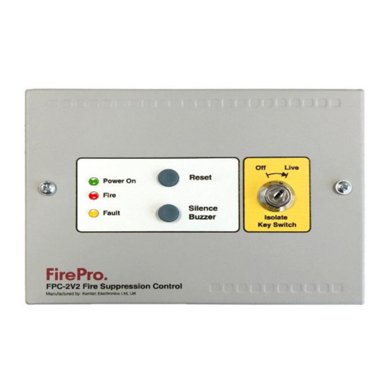
Under normal circumstances, the green Power On indicator will be lit, and the internal buzzer will be silent.
The wiring to the detection circuit and to the FirePro Aerosol Generators is supervised and disconnection of any of
this wiring will be shown by illumination of the yellow Fault indicator on the front panel and operation of the internal
buzzer. The internal fault volt free contact will operate and signal any external equipment that is connected to the
controller Internal indicators are provided to show whether it is the detection circuit wiring or the wiring to the
Aerosol Generators that has a fault.
The buzzer may be silenced by pressing the Buzzer Silence button.
Upon activation of a linear heat detection cable or smoke detector, the red Fire indicator will be lit, the FirePro
Aerosol Generators will operate and immediately discharge extinguishing Aerosol into the protected area, the
internal buzzer will sound and the Fault indicator will illuminate, indicating that the Aerosol Generators have fired
and need replacing.
The internal fire volt free contact will operate and signal any external equipment that is connected to the controller.
The buzzer may be silenced by pressing the Buzzer Silence button. Following a fire activation and replacement of
the FirePro Aerosol Generators the system can be returned to normal operation by operating the Reset button on
the front of the controller.
fp_c2_m5.3
Page 2 of 7
