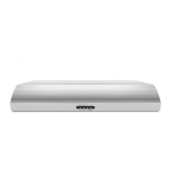
Whirlpool UXT5236AYB1 Installation Instructions And Use & Care Manual - Page 9
Browse online or download pdf Installation Instructions And Use & Care Manual for Ventilation Hood Whirlpool UXT5236AYB1. Whirlpool UXT5236AYB1 32 pages. 30" (76.2 cm) and 36" (91.4 cm) range hood

Rc nge
H@t}d
1. Remove metal grease filter. See the "Range Hood Care"
7. Remove vent knockouts depending on your installation
section,
requirements.
2. Remove the 2 bottom panels.
C
A
A. Bottom panels
a. Push the panel toward the back of the range hood until
the front tabs of the panel clear the front mounting flange.
b. Pull down on the front of the panel and pull the panel
away from the rear channel. Set panels aside.
NOTE: Your model will have a 31¼ '' x 10" (8.3 x 25.4 cm)
rectangular vent damper on the inside your range hood.
3. Remove the 31¼ '' x 10" (8.3 x 25.4 cm) rectangular vent
damper taped on the inside your range hood.
4. Lift the range hood up under cabinet and determine final
location by centering beneath cabinet. Mark on the underside
of cabinet the location of the 4 keyhole mounting slots on the
range hood. Set range hood aside on a covered surface.
A
8.
A. Round vent knockout
B. Top rectangular vent knockout
C. Rear rectangular
vent knockout
Round vent system installations - Remove top rectangular
and round vent knockouts.
Rectangular
vent system installations
- For roof
installations,
remove the top rectangular vent knockout. For
wall installations,
remove the rear rectangular vent knockout.
Non-vent
(recirculating)
installations
- Do not remove any
knockouts.
Install 7" (17.8 cm) round vent mounting plate or 3W' x 10"
(8.3 x 25.4 cm) rectangular vent damper, depending
on your
vent system installation. Attach to range hood with the 3.5 x
5 mm screws provided and remove tape from damper flap.
NOTE: The 7" (17.8 cm) round vent mounting plate is not
supplied. An optional 7" (17.8 cm) round damper is also
available as an accessory. For information
on ordering, see
the "Accessories"
section.
............A
5.
6.
A. Keyhole slot
Use 1/8"(3 mm) drill bit and drill 4 pilot holes as shown.
A
A. Drill pilot hole
Install the 4 - 4.5 mm x 13 mm mounting screws in pilot
holes. Leave about 1/4"(6.4 cm) space between screw heads
and cabinet to slide range hood into place.
\\\\\\\\\\
__
1/4"
(6.4 ram)
D
E
A. 7" (17.8 cm) Round damper (see "Accessories"
section)
B. 3.5 x 5 mm screws
C. 7" (17.8 cm) round vent mounting plate (see
"Accessories"
section)
D. Round vent knockout
E. Rectangular
vent knockout
