CALECTRO CALAIR-PR-230V Installation Instruction - Page 5
Browse online or download pdf Installation Instruction for Controller CALECTRO CALAIR-PR-230V. CALECTRO CALAIR-PR-230V 12 pages.

cover's lower locking device releases. Fit the
cover by carry out the above in reverse order.
INSTALLATION
Hose connections:
There are two hose connections marked plus
(+) and minus (-) on the outside of the enclosure.
Connect the positive pressure hose to plus (+)
and the negative pressure hose to minus (-). See
figure 1.
Electrical installation:
See figure 2.
Connection terminals:
Block
Info
1
Alarm relay (NO)
2
Alarm relay (C)
3
Alarm relay (NC)
4
230V AC
5
230V AC
6
0-10V out GND
7
0-10V out +
8
Temp. input
9
Temp. input
10
RS485 GND
11
RS485 A +
12
RS485 B -
13
Digital input GND
14
Digital input 1
15
Digital input 2
Power is to be supplied to the CALAIR-PR-230V
via a nearby mains switch which is marked:
'Mains switch for CALAIR-PR-230V pressure
regulator'.
TEMPERATURE SENSOR INPUT
The CALAIR-PR-230V has an input for an out-
door temperature sensor. A Pt1000 sensor or a
NTC sensor of the type used with our previous
model, the CALAIR-PR, can be used. Refer
to row 13-16 in the table under Menu System.
Outdoor temperature values can also be written
to the CALAIR-PR-230V via Modbus.
ALARM RELAY, LOG AND ALARM CODES
The alarm relay is activated under normal oper-
ating conditions and de-energizes in the event of
an alarm or power failure.
Alarm codes in alarm log:
01 High pressure alarm
02 Low pressure alarm
03 DI1 motor alarm
04 DI2 motor alarm
05 Temperature sensor error alarm
DIGITAL INPUTS
CALAIR-PR-230V has two digital inputs (DI1
and DI2) which can be programmed for different
functions: motor alarm via the motor's thermal
cut-out or changed force setpoint.
The force setpoint on DI2 is compensated for
outdoor temperature in the same way as the
ordinary setpoint is compensated. The setpoint
on DI1 is however fixed.
Refer to row 41-48 in the table under Menu
System.
MODBUS RTU VIA RS485
CALAIR-PR-230V is prepared for Modbus commu-
nication via RS485. Modbus address, baud rate and
parity are adjustable. Refer to row 54-59 in the table
under Menu System.
The built in pull-up (4k7+) and pull-down (4k7-)
resistance can be used, depending on the system's
Modbus master. The CALAIR-PR-230V also has
built-in termination resistance (120R). See figure 2.
COMMISSIONING
It is recommended that the unit is zero pressure
calibrated the first time the unit is used. Detach all
external pressure hoses and carry out zero pressure
calibration via the programming menu. Refer to row 3
in the table under Menu System.
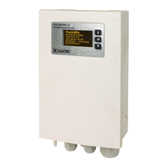
DISPLAY
CALAIR-PR-230V switches off the display after the
normal display mode has been displayed for 200
seconds. Press any button to turn the display back
on.
Display example:
Pressure:148Pa
Setpoint:150Pa
Temp:24.2°C
Output:8.0V
DI1:Open
DI2:Open
Relay:Normal
1: Current pressure: 148 Pascal
2: Setpoint: 150 Pascal
3: Current outdoor temperature: 24.2°C
4: Current output signal: 8.0V DC
5: Digital inputs open
6: Alarm relay: normal operating
MAINTENANCE
CALAIR-PR-230V is normally maintenance free.
Zero pressure calibration can be carried out when
necessary.
RESETTING TO FACTORY SETTINGS
Factory settings are reset via the menu system.
Refer to row 50-52 in the table under Menu System.
A zero pressure calibration must be carried after the
factory settings have been reset. Refer to row 3 in the
table under Menu System.
1
2
3
4
5
6
5
