FIRETRACE 800095-A Installation Manual - Page 15
Browse online or download pdf Installation Manual for Control Unit FIRETRACE 800095-A. FIRETRACE 800095-A 18 pages. Dual pressure switch module with & without bypass
3.7 System Activation
1.
Install the detection tubing throughout the enclosure. Ensure all necessary fittings and accessories are installed in accordance with the
procedures specified in the DIOM of the Firetrace suppression unit being installed
2.
With the unit ball valve in the closed position, thread the tube fitting into the ball valve attached to the top of the cylinder valve.
3.
Install one end of the Firetrace detection tubing into the fitting.
4.
Ensure the end of line adapter is installed at the opposite end of the detection tubing. Verify no accessories are installed in the end of line
adapter.
a.
If using the Dual Pressure Switch Module with the integrated end-of-line adapter, no end-of-line adapter needs to be installed as
part of the detection network.
5.
Attach the filling adapter into the end-of-line adapter.
6.
Attach a regulated nitrogen supply onto the filling adapter.
7.
Pressurize the detection tubing to the suppression unit's operating pressure.
8.
Remove the nitrogen supply and filling adapter from the end-of-line adapter.
9.
Thread the pressure gauge into the end of line adapter and verify that the tubing is pressurized to the correct pressure.
10. With the gauge still installed in the end-of-line adapter, test for leakage:
DIOM 800095-A
Cross threading can occur on the harness connector if connection is forced
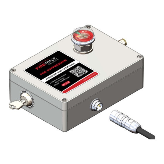
Figure 16 – Cable Harness Install | Exploded View
Figure 17 – Harness Pinout Diagram
Table 6 – Pinout Details
Pin
Wire Color
1
White
2
Brown
3
Green
4
Yellow
Shield
Green/Yellow
CAUTION
Pressure Switch
Supervisory / Activation (PS2)
Supervisory / Activation (PS2)
Activation (PS1)
Activation (PS1)
N/A
11
7/22/2022