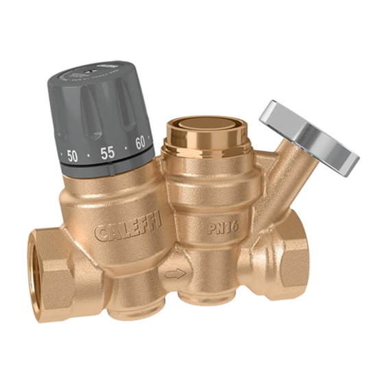
CALEFFI ThermoSetter 116140A Installation, Commissioning And Servicing Instructions - Page 5
Browse online or download pdf Installation, Commissioning And Servicing Instructions for Control Unit CALEFFI ThermoSetter 116140A. CALEFFI ThermoSetter 116140A 13 pages. Recirculation thermal balancing valve
Also for CALEFFI ThermoSetter 116140A: Manual (12 pages), Installation, Commissioning And Servicing Instructions (9 pages)
2
1
Function A - Temperature control
At the set temperature, the valve plug, controlled by the thermostatic balancing cartridge,
gradually closes the outlet to the minimum. The outlet never fully closes to always allow a
minimum flow for temperature sensing and to prevent recirculation pump dead-heading. If the
temperature decreases, the outlet increases, causing flow and thus temperature to increase
back to the set temperature as shown in curve 1. If temperature exceeds the set-point, the
plug stays in the minimum closed position as shown in curve 2. The balancing cartridge has a
throttling range of 60°F, from full open to minimum position.
Thermostatic control
Function B - Automatic thermostatic disinfection
2
The 116
xx series operating characteristic curves for operating mode B are curves 1,
2, 3 and 4. When a temperature higher than about 155°F (68°C) is reached, a by-pass
passage begins to open to activate the second thermostatic cartridge which controls the
thermal disinfection process, allowing flow independent of the operation of the thermostatic
balancing cartridge. This allows water flow through a special by-pass port, opening the flow
path up until the temperature of 160°F (70°C) is attained shown in curve 3. If the temperature
continues rising beyond this point, the flow is reduced through the by-pass port to allow
thermal balancing even during the disinfection process. When temperature reaches about
170°F (75°C), the closes the disinfection by-pass port to protect the system fixtures from the
effects of excessive temperatures, as shown in curve 4.
Thermostatic disinfection
4
5
3
G (gpm)
Temperature control
Cv
max
(2.1)
Cv
dis
(1.2)
Cv
design
(0.52)
Cv
min
(0.23)
Minimum flow rate
Thermal shut-off
5
Thermal disinfection
T
set
Automatic disinfection
C
2
2
1
1
4
4
T (°F)
1
1
3
3
5
5
6
7
6
7
8