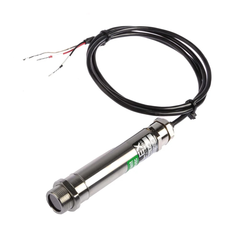
Calex PyroUSB PUA8 Operator's Manual - Page 6
Browse online or download pdf Operator's Manual for Accessories Calex PyroUSB PUA8. Calex PyroUSB PUA8 17 pages. Electronics two-wire 4-20 ma output sensor with a drr245 controller
Also for Calex PyroUSB PUA8: Connecting And Configuring (2 pages)

INSTALLATION
The installation process consists of the following stages:
1
Preparation
2
Mechanical installation
3
Electrical installation
Please read the following sections thoroughly before proceeding with the installation.
PREPARATION
Ensure that the sensor is positioned so that it is focused on the target only.
DISTANCE AND SPOT SIZE
The size of the area (spot size) to be measured determines the distance between the sensor
and the target. The spot size must not be larger than the target. The sensor should be
mounted so that the measured spot size is smaller than the target.
REFLECTIONS
The sensor must be installed in a location where energy from lamps, heaters and sunlight
cannot be reflected from the target into the lens. The use of shields may help in this respect.
For further information and assistance contact Calex.
AMBIENT TEMPERATURE
The sensor is designed to operate in ambient temperatures from 0°C to 70°C. For ambient
temperatures above 70°C, an air/water-cooled housing will be required. Avoid thermal shock.
Allow 20 minutes for the unit to adjust to large changes in ambient temperature.
ATMOSPHERIC QUALITY
Smoke, fumes or dust can contaminate the lens and cause errors in temperature
measurement. In these types of environment the air purge collar should be used to help keep
the lens clean.
ELECTRICAL INTERFERENCE
To minimise electromagnetic interference or 'noise', the sensor should be mounted away from
motors, generators and such like.
6
