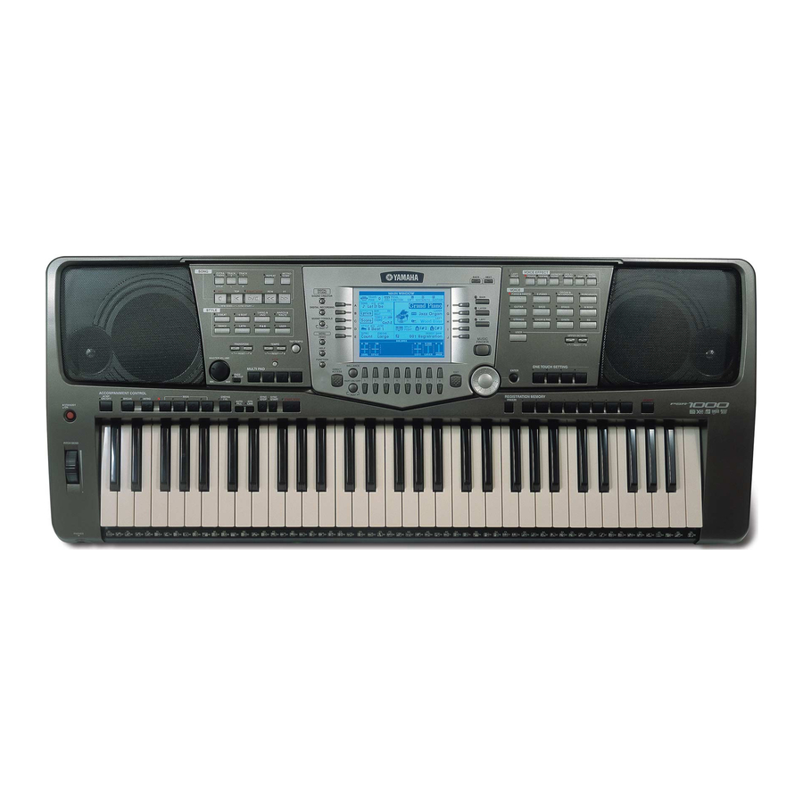
Yamaha PortaTone PSR-2000 Service Manual - Page 10
Browse online or download pdf Service Manual for Musical Instrument Yamaha PortaTone PSR-2000. Yamaha PortaTone PSR-2000 19 pages.
Also for Yamaha PortaTone PSR-2000: Quick Steps (28 pages)

TEST PROGRAM
1. Preparation
1) PA-300 (AC adaptor) is used.
2) The volume is usually moved to the use position when no volume change is required.
3) Measuring instruments: frequency counter, level meter (with JIS-C filter)
Note: Connect a stereo plug to the [PHONES] jack at 33 ohms.
4) Jigs: foot switch (FC-4), foot volume (FC-7), MIDI cable, floppy disk (2HD & 2DD), microphone (PSR-2000 only)
2. How to enter the Test Program
While pressing the [C#2], [F2] and [G#2] keys, turn the [STANDBY/ON] switch on.
3. Proceeding through the Teat Program
When the test program is activated, the sign "TEST" is indicated on the LCD display.
Automatically performs RAM BACKUP check when entering test mode.
Select the test program item to be executed by pressing the [TEMPO-] or [TEMPO+] button.
Press the [START/STOP] button to execute testing. When the test result is OK, press the [START/STOP] button to return to the test
item name on display. Proceed to the next test by pressing the [TEMPO-] or [TEMPO+] button. When the test result is OK, an asterisk
(*) is added in front of its item name on display.
When the test result is NG, press the [DEMO] button or the lowest (leftmost) white key on the keyboard to return to the test item name
on display and then turn off the [STANDBY/ON] switch to end the test program.
4. Test program list
No.
LCD (initial)
1
001: Version
2
002: ROM Check1
3
003: RAM Check1
4
004:Flash Check1
5
005: Wave ROM Check1
6
006: Wave RAM Check1
7
007: FDD Check
9
009: Effect 2 RAM Check
(PSR-2000 only)
10
010: Effect 3 RAM Check
12
012: TG1 Check
15
015: Pitch Check
Test Function and Judgment criteria
Displays each ROM version.
ROM versions are displayed alternately on the LCD.
Checks the ROMs that are connected to the CPU bus.
The test results appear on the LCD. Check the LCD "ROM Check1 OK"
Checks the RAMs that are connected to the CPU bus.
The test results appear on the LCD. Check the LCD "RAM Check1 OK"
Checks the Flash Memories that are connected to the CPU bus.
The test results appear on the LCD. Check the LCD "Flash Check1 OK"
Checks the Wave ROMs.
The test results appear on the LCD. Check the LCD "XG Wave ROM Check OK"
Checks the Wave RAMs.
The test results appear on the LCD. Check the LCD "XG Wave RAM Check OK"
Checks the floppy disk drive unit.
Insert the floppy disks one bye one (2HD or 2DD).
The test will be executed immediately if an FD is inserted in the drive. After completing the test for one FD,
replace it with another to continue the test.
Displays "FDD Check OK" if the test result is OK.
Displays "NO FD" and stands by for FD insertion if an FD is drawn out before completion of the test.
Displays "PROTECT FD" if the write-protect switch of FD is on.
Displays "UNFORMAT FD" if non-formatted FD is inserted.
Checks the VOP3 RAM.
Outputs the sine wave (C3) MAX at the send level and MIN at the drive level.
Check the sound by hearing that there is not noise or abnormal sound.
Checks the XG1 RAM.
Outputs the sine wave (C3) MAX at the send level and MIN at the drive level.
Check the sound by hearing that there is not noise or abnormal sound.
Sequentially outputs the sine wave starting from the low keys (from C2 to G4) by switching the channel of the
sound source.
Check the sound by hearing that there is not noise or abnormal sound.
Pitch check: Connect the frequency counter to the [PHONES] jack (33 ohm load).
Outputs the sine wave at 440.0 Hz +/- 0.22 Hz. (PAN = Center)
Decline quantity check of the volume: Connect the level meter (with JIS-C filter) to the [PHONES] jack. Set the
[MASTER VOLUME] at MIN and check the output level.
PHONES L, R: less than -80.0 dBm
PSR-1000/PSR-2000
39
