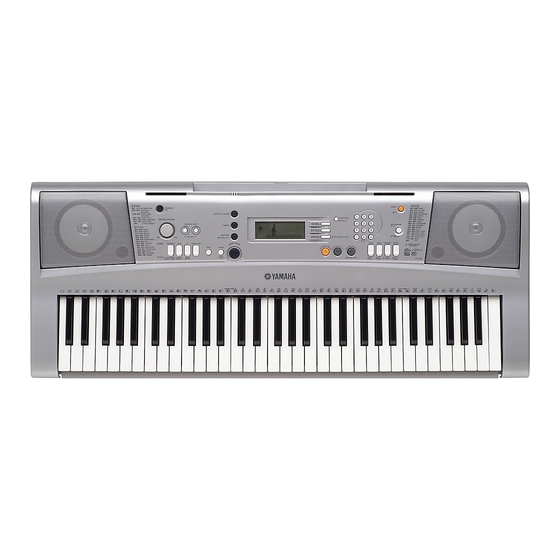
Yamaha PORTATONE PSR-E303 Service Manual - Page 8
Browse online or download pdf Service Manual for Electronic Keyboard Yamaha PORTATONE PSR-E303. Yamaha PORTATONE PSR-E303 36 pages.

PSR-E303/YPT-300
4.
PNAM Circuit Board (1/3, 2/3, 3/3)
4-1
Remove the lower case assembly. (See procedure 1)
4-2
PNAM Circuit Board 3/3
(Time required: About 2 minutes)
4-2-1 Remove the volume knob from the control panel
surface. (Fig. 1, 3)
4-2-2 Remove the three (3) screws marked [150A]. The
PNAM circuit board 3/3 can then be removed. (Fig. 2)
4-3
PNAM Circuit Board 1/3
(Time required: About 3 minutes)
4-3-1 Remove the PNAM circuit board 3/3.
4-3-2 Remove the twelve (12) screws marked [150B]. The
PNAM circuit board 1/3 can then be removed. (Fig. 2)
4-4
PNAM circuit board (2/3)
(Time required: About 3 minutes)
4-4-1 Remove the nine (9) screws marked [150C]. The
PNAM circuit board 2/3 can then be removed. (Fig. 2)
Bottom view
[30]
[240C]
Lower Case Keyboard Assembly
[30]: Bind Head Tapping Screw-B 4.0X8 MFZN2Y (EP640410)
[150]: Bind Head Tapping Screw-B 3.0X8 MFZN2Y (EP600250)
[240]: Bind Head Tapping Screw-B 3.0X12 MFZN2Y (VE683000)
[270]: Bind Head Tapping Screw-B 3.0X30 MFZN2Y (V7213700)
8
[A]
[150C]
PNAM
2/3
[150C]
[270B]
(Fig.2)
Rubber Connector
Conductor side
Rubber Connector
5.
Speaker
5-1
Remove the lower case assembly. (See procedure 1)
5-2
Remove the four (4) screws marked [30]. The
speaker can then be removed. (Fig. 2)
∗
The right and left speakers can be removed in the
same way.
6.
SP Grille
6-1
Remove the lower case assembly. (See procedure 1)
6-2
Set the four (4) [A]s parallel to the groove in the upper
case assembly and remove the SP grille. (Fig. 2)
∗
The right and left SP grilles can be removed in the
same way.
[240B]
[150B] [150A]
3
4
5
6
PNAM
DMLCD
1/3
1
7
8
2
[240B]
[150B]
DMLCD
(Fig.4)
(Time required: About 3 minutes)
(Time required: About 3 minutes)
PNAM
[30]
[150B]
3/3
[240C]
Knob
(Master Volume)
(Fig.3)
LCD
Back Light Assembly
Rubber Connector
LCD Holder
[A]
