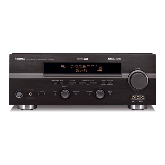
Yamaha HTR-5740 Service Manual - Page 33
Browse online or download pdf Service Manual for Receiver Yamaha HTR-5740. Yamaha HTR-5740 39 pages. Av receiver/av amplifier

- 1. Contents
- 2. Service Manual
- 3. Set Menu Table
- 4. Internal View
- 5. Block Diagram
- 6. Printed Circuit Board (Foil Side)
- 7. Schematic Diagram
- 8. Schematic Diagram (Operation)
- 9. Schematic Diagram (Main)
- 10. Schematic Diagram (Power)
- 11. Schematic Diagram (Subtrans)
- 12. Schematic Diagram (Video)
- 13. Exploded View
A
B
C
RX-V550/HTR-5750/RX-V450/HTR-5740/DSP-AX450
SCHEMATIC DIAGRAM (MAIN)
1
Page 83
F10
55.3
to POWER (1)
55.3
1.1
0.6
0.6
1.1
-0.4
-1.0
0.6
-0.5
2
-0.5
-1.0
-0.5
-52.8
-1.0
-55.2
-55.3
-53.3
-53.9
55.3
55.3
1.1
0.5
0.5
3
1.1
0
-0.4
0.5
-1.0
-0.5
0
-0.5
-0.5
-1.0
-1.0
-55.3
-55.3
-52.7
FRONT L
-53.3
-53.3
-53.9
4
SURROUND L
55.3
55.3
1.0
0.5
1.0
0.5
-0.4
-1.0
Page 83
E10
to POWER (1)
-0.5
-1.0
-1.0
-0.5
-55.2
-55.2
-52.7
5
-53.3
-53.3
Page 83
E10
to POWER (1)
-53.9
55.3
55.3
1.0
0.5
1.0
0.5
-0.4
CENTER
-1.0
6
0
-0.5
-0.5
-1.0
-1.0
-55.2
-55.2
-52.7
-55.3
-53.3
-53.9
55.3
1.0
55.3
0.5
1.0
-0.4
0.5
7
-1.0
-0.5
-0.5
-1.0
-1.0
-55.2
-52.2
-52.8
-55.3
-53.3
-53.9
8
55.3
55.3
1.0
0.5
1.0
0.5
-0.4
-1.0
-0.5
-0.5
-1.0
-1.0
-55.2
-55.2
-52.8
-53.3
9
-53.3
-53.9
54.9
54.6
-54.9
-53.9
-53.9
55.2
54.6
-54.5
-55.5
55.2
-55.0
0
0.3
0
-55.5
0.3
0
0
10
82
D
E
F
55.3
55.2
0.1
0
55.0
0
0
0
0
0
0
4.7
0
0
-55.2
0
0
0
0
0
0
0
0
0
0
0
55.0
0
0
0
0
0
55.0
0
0
0
0
0
55.0
0
0
0
0
0
55.0
0
0
0
0
0
0
55.0
0
0
0
0
0
0
-47.6
-13.2
-13.8
-13.8
0
G
H
I
RX-V550: Page 77
H7
HTR-5750, RX-V450, HTR-5740,
DSP-AX450: Page 79
H8
to FUNCTION (2)
SPEAKER RELAY
24.8
24.8
24.9
12.3
12.5
24.8
35.3
12.5
0.1
0.2
0.1
34.8
12.5
0.2
35.3
0.1
0.8
35.3
0
24.8
0
0.2
0
0.8
0
36.1
0.1
0.8
0
-36.5
-28.4
-29.0
0
Page 83
K3
to POWER (1)
55.3
0
0
55.3
0.1
48.2
3.6
4.8
55.3
0
55.3
-48.5
0.1
-48.5
1.3
2.5
0
-55.2
55.3
0
RX-V550: Page 77
H6
Page 84
A4
to SUBTRANS
HTR-5750, RX-V450, HTR-5740,
DSP-AX450: Page 79 H7
to FUNCTION (2)
J
K
RX-V550/HTR-5750
U,C
s1
C130, 131, 134-137
X
s2
TE120, 121
WC63190
s4
C138-141
X
s6
SW1
SS029-P022MJB
V362430
s7
C122, 123
10000/71
WC91080
RX-V450/HTR-5740/DSP-AX450
J
U,C
s1
C130, 131, 134-137
X
X
s2
TE120, 121
WC63190
WC63190
s4
C138-141
X
X
s6
SW1
X
SS029-P022MJB
V362430
s7
C122, 123
8200/71
8200/71
WB12720
WC91090
x: NOT USED
O: USED / APPLICABLE
36.1
0
0
36.1
0
0
-36.5
-55.2
0
-55.2
48.2
-3.7
-3.8
-3.7
2.5
3.6
0
0
-55.2
-3.7
-55.2
-3.7
-3.7
1.3
0.1
0.8
0
AC55.0
to Power Transformer
AC81.9
L
M
N
R,T,A
B,G,L,K,E
0.01
0.01
UA65410
UA65410
WC63190
WC63180
4700P
4700P
UA65347
UA65347
SS029-P022MJB
SS029-P022MJB
V362430
V362430
10000/71
10000/71
WC91080
WA74430
R,T,A
B,G,L,K,E
0.01
0.01
UA65410
UA65410
WC63190
WC63180
4700P
4700P
UA65347
UA65347
SS029-P022MJB
SS029-P022MJB
V362430
V362430
8200/71
8200/71
WC91090
WB12720
# All voltages are measured with a 10MΩ/V DC electronic volt meter.
# Components having special characteristics are marked s and must be replaced
with parts having specifications equal to those originally installed.
# Schematic diagram is subject to change without notice.
s
