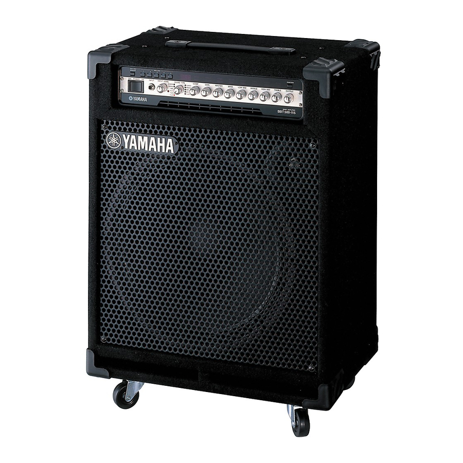
Yamaha BBT500-115 Owner's Manual - Page 8
Browse online or download pdf Owner's Manual for Amplifier Yamaha BBT500-115. Yamaha BBT500-115 21 pages. Preset patch list
Also for Yamaha BBT500-115: Supplementary Manual (1 pages)

Panel Controls and Connections
Rear Panel
Outboard Effects Processor
!4
Tuner
External Speaker(s)
!4 Tuner Output (TUNER OUT)
This output jack is used to connect a tuner to the BBT500.
It can also be used to create a bi-amp system. Connect this output jack
to the INPUT jack on another BBT500. (→ pg. 15)
!5 Effect Loop (FX LOOP)
• Effect Send Jack (SEND)
• Effect Return Jack (RETURN)
• Effect Loop Level Switch (LEVEL)
These jacks let you insert an outboard effects processor between the
SEND and RETURN jacks to apply effects to the BBT500's signal.
Use the Level Switch to match the Input/Output level with the level re-
quired by the outboard effects processor. Use the BLEND control in the
Compressor Mode to adjust the balance level between the outboard
effector's sound and the sound that is created by the BBT500. (→ pg.
14)
8
Before making any connections, make sure that the power on
the BBT500 and all other related devices is switched OFF.
Mixer or Additional Amplifier
Headphones
IN
OUT
!5
!6 !7
@5
Clamp Filter (→ pg. 10)
* For U.S. and Canadian
models only
Save patches to a
!8
!9
@0
@1
@2
Internal Speaker
@6
!6 Headphones Jack (PHONES)
This jack is used to connect a pair of headphones to the unit. It carries
the same signal that is delivered from the LINE OUT jack. Use the LEVEL
control to adjust the volume.
!7 Headphones/Line Out Level Control (LEVEL)
Adjusts the output level of the PHONES jack and the LINE OUT jacks.
(The same setting is applied to both jacks.)
!8 Line Out Jack (UNBALANCED OUT)
!9 Line Out Jack (BALANCED OUT)
These jacks carry the signal that is selected with the @0 Line Out Source
Switch at a line level.
Both unbalanced phone type (+4 dB/10 kΩ) and balanced XLR type
(+4 dB/600 Ω) jacks are provided.
Use the LINE SOURCE switch to select the signal that is sent to the
LINE OUT jack. As the unit is equipped with an output limiter and speaker
simulator (can be switched ON/OFF), and the output level of these jacks
is controlled by the LEVEL control, these jacks can be used to send a
line level signal to a mixing console or an additional amplifier.
Use a MIDI controller to select
MIDI device
patch memory
STATUS
BANK MSB/MAX
8. 8 . 8
.
DATA/CTRL
BANK LSB/MIN
TOGGLE ON-OFF
/NUMBER OF PGM
DEC
±10
INC
MEMORY
/NO
/YES
EDIT
MIDI OUT
MIDI IN
@3
@4
@7
Supplied power
cable
AC Power
PC
WRITE
EDIT
/EXIT
