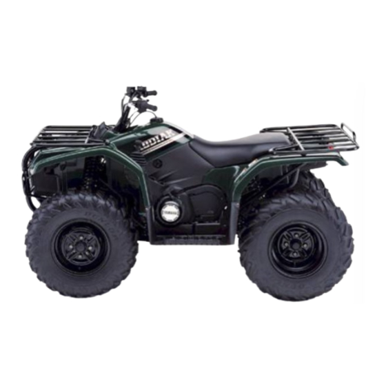
Yamaha 2000 YFM400FWAM Assembly Manual - Page 15
Browse online or download pdf Assembly Manual for Offroad Vehicle Yamaha 2000 YFM400FWAM. Yamaha 2000 YFM400FWAM 42 pages.
Also for Yamaha 2000 YFM400FWAM: Service Manual (31 pages)

17. Rear wheel (right)/Roue arrière (droit)
18. Rear wheel (left)/Roue arrière (gauche)
1
Rear wheel
2
Wheel hub
3
Nut
4
Plain washer
5
Castle nut
6
Cotter pin
7
Wheel cap
A: Tighten the nuts to specified
torque.
WARNING
Install the nut with its tapered side
towards the wheel.
Tightening torque:
55 Nm (5.5 m • kg, 40 ft • lb)
B: Install the wheel so that air
valve is outside.
C: The arrow mark on the tire must
point toward the rotating
direction of the wheel.
D: Tighten the nuts to specified
torque.
Tightening torque:
150 Nm (15 m • kg, 110 ft • lb)
E: Bend the end of the cotter pin.
1
Wheel cap
2
Rear wheel
3
Nut
A: Install the wheel so that air
valve is outside.
B: The arrow mark on the tire must
point toward the rotating
direction of the wheel.
C: Tighten the nuts to specified
torque.
WARNING
Install the nut with its tapered side
towards the wheel.
Tightening torque:
55 Nm (5.5 m • kg, 40 ft • lb)
–8–
1
S
1
C
4
V
d = 10 (0.39)
1
V
d = 16 (0.63)
1
V
d = 16 (0.63)
1
V
1
V
A: Serrer les écrous selon le couple
spécifié.
AVERTISSEMENT
Monter la roue avec son côté
conique orienté vers la roue.
Couple de serrage:
55 Nm (5,5 m • kg, 40 ft • lb)
B: Placer la roue de sorte que la
valve soit à l'extérieur.
C: Le repère fléché du pneu doit être
orienté dans le sens de rotation
de la roue.
D: Serrer les écrous selon le couple
spécifié.
Couple de serrage:
150 Nm (15 m • kg, 110 ft • lb)
E: Courber l'extrémité de la
goupille fendue.
1
V
1
S
4
V
d = 10 (0.39)
A: Placer la roue de sorte que la
valve soit à l'extérieur.
B: Le repère fléché du pneu doit être
orienté dans le sens de rotation
de la roue.
C: Serrer les écrous selon le couple
spécifié.
AVERTISSEMENT
Monter la roue avec son côté
conique orienté vers la roue.
Couple de serrage:
55 Nm (5,5 m • kg, 40 ft • lb)
