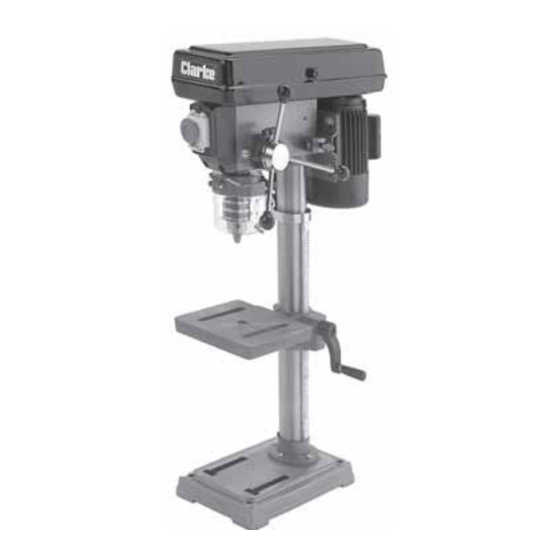
Clarke CDP10B Operating & Maintenance Instructions - Page 9
Browse online or download pdf Operating & Maintenance Instructions for Power Tool Clarke CDP10B. Clarke CDP10B 19 pages. 12 speed drill press

ASSEMBLY
IT IS ADVISED THAT ASSISTANCE BE USED WHEN ASSEMBLING THIS MACHINE.
NOTE: Ideally, the base should be firmly bolted to a workbench, or floor, prior to the assembly of
other components. The mounting surface must flat, level, and capable of supporting the weight of
the drill plus anticipated work.
Floor mounting should be by proper foundation bolts, minimum size- M10. If necessary, consult
a qualified engineer to ensure installation is sound.
CDP10B - Bench model should be bolted to a suitably constructed workbench, using minimum
size M10 bolts.
Before assembly, remove all traces of preservative from the components with paraffin or a good
quality solvent, and wipe all parts thoroughly with a clean dry cloth. Apply a coating of wax
paste or light oil to the table, column and base, to prevent rust.
A.
Column to the Base.
Bolt the column assembly to the base with the four
hex. screws provided.
B. Mounting the Table Assembly
1. From the box of loose parts, locate the worm, and
install it in the gear housing of the table support,
liberally greased and pushed fully home - see Fig.1.
2. Push the crank on to the worm spigot, protruding
from the gear housing, as far as it will go and
tighten the crank's grub screw on to the flat on the
spigot.
3. Slacken the grub screw, securing the collar to the
column - see Fig.2, and pull collar and rack from
off the column completely.
4. Slide the rack into the table support with the long,
smooth end uppermost, so that the gear teeth
engage with the worm, as shown in Fig.3, and
holding in this position, slide the table support, with
rack, on to the column.
5. Lower the table support so that the end of the rack
sits fully into the groove made by the column
support on the base, and the column, then
replace the collar on to the column, with the
groove, machined on its inner periphery, facing
downwards.
6. With the rack sitting snugly in the grooves, top and
bottom, tighten the collar grub screw ensuring
there is sufficient clearance to allow the complete
table assembly to move about the column.
Apply a film of grease to the groove in the base and
collar in which the ends of the rack sits.
7. Check to ensure the table moves smoothly from top to
bottom of the rack, and if necessary ease off the rack
collar by slackening the grub screw and repositioning
the collar in order to achieve this.
CAUTION!
9
Fig. 1
Fig. 2
Fig. 3
