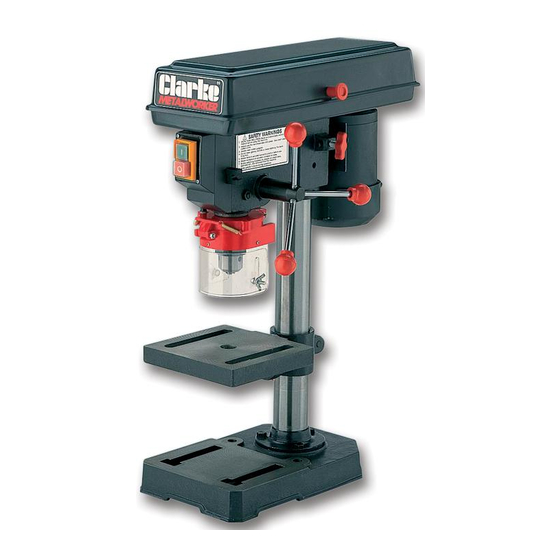
Clarke Metalworker CDP101B Operating & Maintenance Manual - Page 12
Browse online or download pdf Operating & Maintenance Manual for Power Tool Clarke Metalworker CDP101B. Clarke Metalworker CDP101B 19 pages. 13mm drill press

2. Spindle Depth Stop
On the left side of the drill head, is the Spindle Feed (or Depth Feed) adjuster assembly,
which allows the depth of hole to be set. For setting a particular depth, proceed as follows:
1.
Lower the Chuck - with the power OFF, until the drill bit contacts the surface of the
workpiece, and hold in that position.
2.
Spin down the adjuster nut (B), so that the gap between its' underside, and face E, is
the depth of the hole required. Spin down nut C and lock it against B.
The drill is now set to drill holes to your predetermined depth, from that particular start
point. i.e. Providing the surface of your workpiece is flat and level, you may drill a series
of holes, each to the same depth quickly and accurately.
The Scale and pointer can be used to drill one off, by lowering the chuck, with the
power OFF, until the drill bit contacts the work, setting the pointer to a chosen mark on
the scale, switching ON the drill, and proceeding to drill to the required depth past your
chosen mark.
3. Changing Drill (Spindle) Speed.
Before changing the speeds, ensure the
machine is switched OFF, and disconnected
from the mains supply.
1.
Open the pulley cover.
2.
Slacken off the Belt Tension Locking
Screw, to relieve any tension on the
drive belt (see fig.5).
3.
Consult the chart inside the pulley cover,
and position the belt on the pulley's,
according to the spindle speed required.
4.
When the belt has been correctly positioned, re-tension by levering the motor away
fromthe head, until the belt deflects by approx. ½" at its centre when using reasonable
thumb pressure. Lock the motor in this position with the Belt Tension Locking Screw.
DRILL SPEED TABLE
The table below gives the belt arrangement for given drill speeds. The diagram shows the
belts fitted to step D of the Spindle Pulley - 4 of the Motor Pulley, giving a drill speed of 1,900
RPM.
Spindle
Belt
Speed
Position
(RPM)
500
A1
890
B2
1400
C3
1900
D4
2500
E5
(All references are to Fig. 7)
A full chart is also located on the inside of the pulley cover.
SPINDLE PULLEY
E
D
C
B
A
12
Fig. 11
MOTOR PULLEY
5
4
3
2
1
