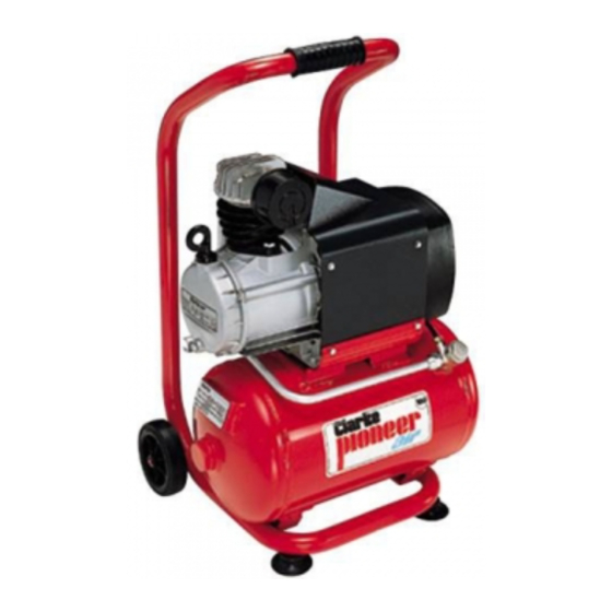
Clarke AIR PIONEER 100 Operating And Maintenance Instructions Manual - Page 5
Browse online or download pdf Operating And Maintenance Instructions Manual for Air Compressor Clarke AIR PIONEER 100. Clarke AIR PIONEER 100 8 pages.

SPARE PARTS
No.
Description
1
Screw ....................................................................... 4 ........... FN014002026
2
Head ....................................................................... 1 ........... FN116034010
3
Intake Filter ............................................................. 1 ........... FN317007000
4
Head Gasket .......................................................... 1 ........... FN116011037
5
Valve Holder Plate ................................................. 1 ........... FN116034100
6
Cylinder Gasket ..................................................... 1 ........... FN113113034
7
Cylinder ................................................................... 1 ........... FN116034006
8
Screw ....................................................................... 2 ........... FN014011064
9
O-Ring ..................................................................... 1 ........... FN010114000
10
Piston Ring Set ........................................................ 1 ........... FN216011003
11
Piston ....................................................................... 1 ........... FN116011027
12
Circlip ...................................................................... 2 ........... FN015001000
13
Gudgeon Pin .......................................................... 1 ........... FN113113003
14
Complete Piston .................................................... 1 ........... FN416011027
15
Connecting Rod .................................................... 1 ........... FN116091021
16
Oil Dipstick .............................................................. 1 ........... FN012036000
17
Complete Casing Cover ...................................... 1 ........... FN116032014
18
Cover Gasket ......................................................... 1 ........... FN116001025
19
Crankshaft .............................................................. 1 ........... FN116034004
20
Casing ..................................................................... 1 ........... FN116022051
21
Screw ....................................................................... 2 ........... FN116011038
22
Overload Reset 240V ............................................ 1 ........... FN008035000
22
Overload Reset 110V ............................................ 1 ........... FN008015000
23
Capacitor 240V ..................................................... 1 ........... FN009200014
23
Capacitor 110V ..................................................... 1 ........... FN009200026
24
Bearing .................................................................... 1 ........... FN033018000
25
Rotor ........................................................................ 1 ........... FN034045000
26
Stator 240V ............................................................. 1 ........... FN416035605
26
Stator 110V ............................................................. 1 ........... FN416085601
27
Bearing .................................................................... 1 ........... FN033118000
28
Rear Cover ............................................................. 1 ........... FN116011002
29
Fan ........................................................................... 1 ........... FN116001003
30
Housing ................................................................... 1 ........... FN199100070
31
Set Of Gaskets ....................................................... 1 ........... FN216GE0101
Qty
Part No
12
ELECTRICAL CONNECTIONS
Connect the mains lead to a standard, 230 Volt (50Hz) electrical supply through
an approved 13 amp BS 1363 plug, or a suitably fused isolator switch.
WARNING! THIS APPLIANCE MUST BE EARTHED
IMPORTANT: The wires in the mains lead are coloured in accordance with the
following code:
Green & Yellow
Blue
Brown
As the colours of the flexible lead of this appliance may not correspond with the
coloured markings identifying terminals in your plug proceed as follows:
•
Connect GREEN & YELLOW cord to terminal marked with a letter "E" or Earth
symbol "
" or coloured GREEN or GREEN & YELLOW.
•
Connect BROWN cord to terminal marked with a letter "L" or coloured RED.
•
Connect BLUE cord to terminal marked with a letter "N" or coloured BLACK.
If this appliance is fitted with a plug which is moulded onto the electric cable (i.e.
non-rewireable) please note:
1.
The plug must be thrown away if it is cut from the electric cable. There is a
danger of electric shock if it is subsequently inserted into a socket outlet.
2.
Never use the plug without the fuse cover fitted.
3.
Should you wish to replace a detachable fuse carrier, ensure that the correct
replacement is used (as indicated by marking or colour code).
4.
Replacement fuse covers can be obtained from your local dealer or most
electrical stockists.
FUSE RATING
The fuse in the plug must be replaced with one of the same rating (13 amps) and
this replacement must be approved to BS1362.
We recommend that this machine is connected to the mains supply via a Residual
Current Device (RCD)
If in any doubt, DO NOT attempt any connections or repairs yourself. Consult a
qualified electrician, your Clarke dealer, or CLARKE International Service Dep't on
020 8988 7400 or e-mail: [email protected]
PIONEER 110 Volt model
Connect the mains lead to a suitable 110V (50Hz) electrical supply through an
approved plug or a suitably fused isolator switch.
If using a portable 110V transformer, make sure it has a rated capacity sufficient
to take a 13 amp load.
-
Earth
-
Neutral
-
Live
5
