Directed Xpresskit DBALL2 Installation Manual - Page 7

Browse online or download pdf Installation Manual for Door locks Directed Xpresskit DBALL2. Directed Xpresskit DBALL2 20 pages. Ford5 remote start ready (rsr) installation
Also for Directed Xpresskit DBALL2: Installation Manual (12 pages), Installation Manual (19 pages), Installation Manual (18 pages), Manual (14 pages), Installation Manual (13 pages), Installation Manual (14 pages), Installation Manual (19 pages), Installation Manual (16 pages), Installation Manual (15 pages), Installation And Quick Reference Manual (16 pages), Installation Manual (18 pages), Installation Manual (16 pages), Installation Manual (18 pages), Installation Manual (16 pages), Manual (19 pages)
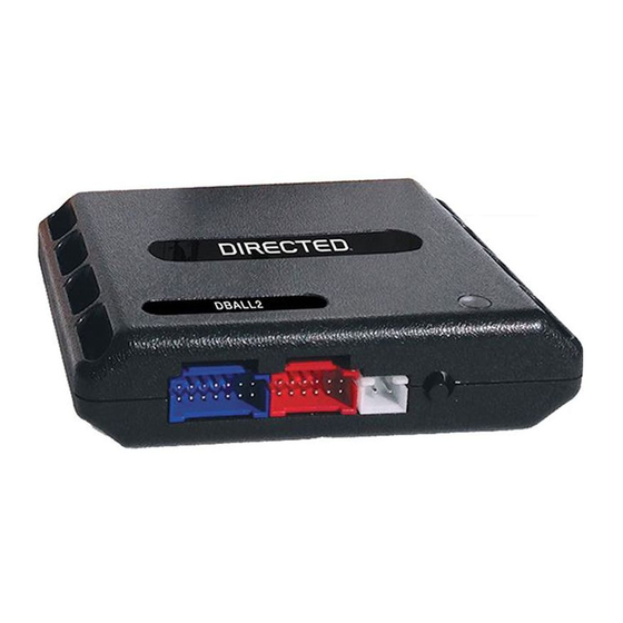
Directed Xpresskit DBALL2 Installation Manual
Platform: DBALL2
Firmware FORD3 emote Start
:
R
Installation Type 2
Important!
The
Hood Pin and Remote Start Safety Override Switch are mandatory safety
C3371 Backup Transceiver
(inside rear of center console)
5
4 3
2 1
Immo. Clock:
Immo. Data:
Yellow/Gray or White,
White/Blue or Blue,
pin 4
pin 3
CUT
With the exception of the
OBDII
Ready (R
SR Installation
C2280C connector
at BCM
(passenger kick panel)
13
26
12
25
Driver Door
Trigger
:
11
24
Green/Violet or Violet,
pin 9
10
23
9
22
8
21
CUT
7
20
6
19
5
18
4
17
3
16
2
15
1
14
MS CAN High:
MS CAN Low:
HS CAN High:
Orange/Green 5
HS CAN Low:
Orange/Brown 6
Immo. Inter. (conn. side):
Immo. Inter. (veh. side):
Orange/Yellow:
RAP Off Interr. (conn. side):
Orange/Red:
RAP Off Interr. (veh.side):
Yellow/Red:
(+) 12V
(-) Ground
(+) Brake Output:
(+)
Parking Lights
Output:
(+)
Push-to-Start
Output
:
Violet/Brown
Immo. Clock
:
Yellow/Black
Immo. Data (
conn
. side)
:
Orange/Black
Fuse 10A
85
86
87
87a
30
32
31
28
29
30
26 25 24 23 22
21 20 19
(+) 12V:
26
15
14
13
12
11
10
9
Red, pin 6
4
3
5
2
6
C2280
D c
onnector
(passenger kick panel)
Diagno tic connector, all adapters are displayed from the wire side (unless specified otherwise).
s
)
devices, but
CAN High:
White
pin 6
1
9
Diagnostic
CAN Low:
connector OBDII
Brown, pin 14
(connector side view)
(+)
PTS Brown/Violet
or Blue/ White, pin 41
Violet/White, pin 28
Tan/Black
: 3
Tan
: 4
:
:
Yellow:
8
9
10
11
Input:
Red
:
13
:
Black
:
14
Gray
: 6
Gray/Black
:
7
:
9
:
10
:
11
RF
Prog. Button
LED
(+) Parking Lights:
Yellow/Green or Violet/White
pin 18
27
18
17
8
7
1
at BCM
are NOT
supplied with the
8
16
C2280B onn
c
:
(passenger kick panel)
(+) Brake:
40
41
42 43 44 45 46 47 48 49 50
27
28
29 30 31 32 33 34 35 36 37
14
15
15
16
17
18
19
20
21
22
23
24
1
2
3
4
5
6
7
8
9
10
11
MS CAN High:
Gray or
Gray/Orange,
pin 38
Hood Pin
Required only when factory
hood pin is not available.
Remote Start Safety
Override Switch
6:
White/Black:
(-) Hood Input
DBALL
2
You can connect to either a
RFTD
OR
a SmartStart module.
Refer to the SmartStart/
XL
Installation Notes for more information.
© 2017 Directed. All rights reserved.
Rev.: 20170908
Page 7
interface
.
ector at BCM
51
52
38
39
25
26
12
13
MS CAN Low:
Violet or
Violet/Orange,
pin 39
XL
202
202