Alemite 7896 Series Service Manual - Page 13
Browse online or download pdf Service Manual for Water Pump Alemite 7896 Series. Alemite 7896 Series 16 pages. Medium-pressure material pump
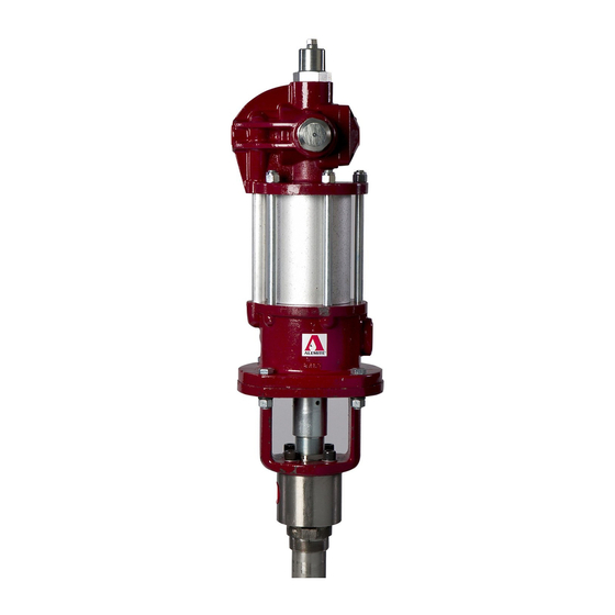
Medium-Pressure Material Pump
27. Install Bung Adapter (29) onto the Extension Cylinder.
28. Screw Coupling (32) onto the Extension Cylinder
(with Loctite 222).
• Do not tighten at this time.
Valve Seat and Guide Assembly
29. Install the Valve Seat and Guide assembly onto
Extension Rod (33) until the Spring Clip holes align.
30. Install Spring Clip (10).
IMPORTANT: Make sure O-Ring (42) fits in
the groove at the shoulder of Extension Cyl-
inder (43). See Figure 6.
31. Install O-Rings (42) onto each end of Cylinder (43).
CAUTION
Use care installing the Cylinder into the Coupling.
Damage to the V-Packings can occur.
32. Screw the Cylinder (knurled end first)
[with Loctite 222] into the Coupling.
• Do not tighten at this time.
Valve Body
33. Install Ball (46) into the top of Valve Body (47).
34. Install and seat Washer (45) and Stop Washer (44)
[convex upward] into the Valve Body.
35. Screw the Valve Body assembly onto the Cylinder
(with Loctite 222).
• Make sure the Ball moves freely.
36. Place a large wrench or other suitable tool into the slot
of the Valve Body.
• Tighten all the components of the assembly securely.
37. Install Tag (18) and Hydraulic Fitting (17) as required.
38. Screw Valve Seat (20) [with Screw (21)] into the Body
as required.
• Make sure the bleed hole points downward.
Attach Air Motor to Pump Tube
39. Extend Rod (11) from the top of the Body assembly
until it locks.
IMPORTANT: Do not overtighten Screw
(12). The pump must cycle with an initial air
pressure setting of 15 psi (1 Bar).
Alemite Corporation
40. Tighten Packing Screw (12) into Plate (15) until it
contacts the V-Packing group.
• Use the torque bar to snug the installation.
41. Screw upper Coupling (9) onto the Rod until the
Spring Clip holes align.
42. Install Spring Clip (10).
43. Position the pump assembly vertically in a soft-jaw
vise.
44. Fill the cavity of the Packing Screw with oil.*
NOTE: If Teflon V-Packings are used, fill
the Screw cavity with a solution that pre-
vents product from drying on the Rod.
This step is important for visual feedback due to
possible leakage during the initial start up procedures.
45. Place a wood block (2" x 4") onto the surface of the
Upper Mounting as illustrated in Figure 6.
46. Position Air Motor Assembly (2) onto the Pump Tube
Assembly and block.
• Make sure to orient the Air Motor Assembly
properly.
47. Screw the air motor piston rod onto the Coupling until
the Spring Clip holes align.
48. Install the Spring Clip.
49. Remove the block and position the Air Motor
Assembly onto the Pump Tube Assembly.
50. Install Screws (5), Lock Washers (7), and Nuts (8) that
secure the Air Motor Assembly to the Pump Tube
Assembly.
• Tighten the Screws securely in a crisscross pattern.
* Refill the cavity at each pump changeover. Note that
oil may overflow the opening of the Packing Screw on
initial start-up. This is due to the position of Rod (11)
[not at top dead center].
13
SER 7896-A5
Revision (2-04)