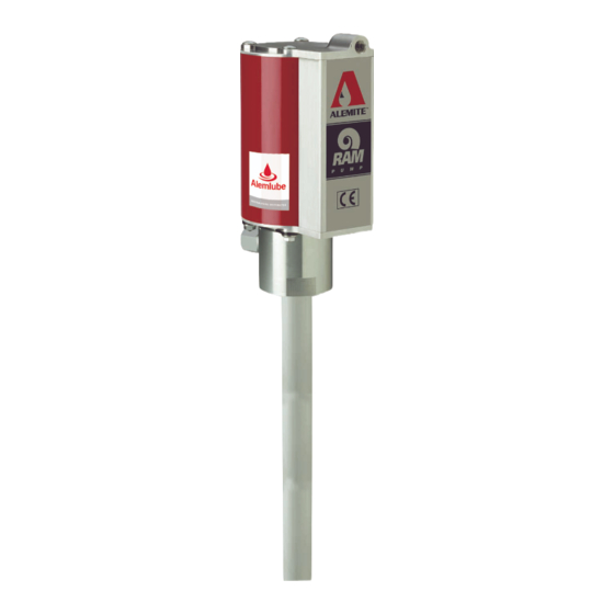
Alemite 9911-R1 Owners Service Manual - Page 4
Browse online or download pdf Owners Service Manual for Water Pump Alemite 9911-R1. Alemite 9911-R1 16 pages. High-pressure stripped pump
Also for Alemite 9911-R1: Service Manual (12 pages), Service Manual (12 pages)

Pumptube assembly
Air\piston
1 Remove nut (2) and washer (3) that
secures air piston (4) to rod (9). Place a
punch or similar tool into the rod to
prevent its rotation († fig. 2-A).
2 Remove the air piston from the rod.
3 Remove quad-ring (5) from the air
piston.
4 Remove o-ring (6) and washer (7) from
the rod.
Body assembly
1 Unscrew Upper Tube (18) from the Body.
2 Remove the Body assembly from the
Rod.
3 From inside the Body remove:
– Gasket (16)
– Bearing (15)
– Seal (14)
– Lantern Ring (13)
– Seal (12)
Tube assembly
1 Push the rod assembly downward
through uppertube (18) until primer disk
(35) protrudes from primer body (42).
2 Remove roll pin (36) that secures the
primer disk to primer rod (34).
3 Remove the primer disk from the primer
rod.
4 Remove the entire rod assembly from
the top of the upper tube.
5 Remove roll pin (25) thatsecuresthe
primer rod to piston (24).
6 Unscrew the primer rod from the piston.
Step for model 9911-1 only
7 Remove roll pin (25) that secures rod (9)
to the piston.
8 Unscrew the piston from the rod.
Step for all models except
9911-1
9 Remove roll pin (25) that secures rod (9)
to the extension.
10 Unscrew the extension from the rod.
11 From inside the piston remove: spring
guide (21), spring (22), ball (23).
12 Unscrew the uppertube from lower
tube (29). Use a strap wrench.
Lower tube
1 Remove gasket (28), bearing (26),
seal (27), and additional bearing (26)
from the lowertube.
Primer body
1 Unscrew primer body (37) from the
lowertube.
2 From inside the lowertube remove:
gasket (28), seat (33), additional
gasket (28), foot valve (32)
[with seal (31)], stop (30).
3 Remove the seal from the foot valve.
Clean and inspect
1 Clean all metal parts in cleaning solvent.
The solvent should be environmentally
safe.
2 Inspect all parts for wear and/or damage.
3 Replace as necessary.
4 Inspect air piston (4) for fatigue cracks.
5 Replace as necessary.
6 Inspect rod (9), piston (24), and primer
rod (34) closely. Use a magnifying glass to
detect any score marks.
7 Replace as necessary.
8 Closely inspect the mating surfaces of all
check valve components for any imperfec-
tions. Ensure a smooth and clean contact
is obtained when assembled.
EXAMPLE
Place Ball (23) into Piston (24). Fill the Piston
with solvent. Make sure no leakage occurs.
4
Assembly
NOTE
Prior to assembly, certain components
require lubrication. Refer to table 3 for
details. Refer to fig. 4 for a section view of the
pump tube assembly.
Lubricated components
Item
Description
Clean oil
5
Quad-ring, 2
/
in. ID x 3 in. OD
5
8
6
O-ring,
/
in. ID x
3
1
8
8
O-ring, 2
/
in. ID x 3 in. OD
3
4
12
Seal,
/
in. ID x
/
1
3
2
4
14
Seal,
/
in. ID x
/
1
7
2
8
17
O-ring, 2
/
in. ID x 2
9
16
27
Seal, 5/8 in. ID x 1 in. OD
31
Seal, 0.282 in. ID x 0.532 in. OD
Magnalube
-G PTFE grease
®
1)
Coat bore of air motor assembly
Part number 393590 is a 0.75 Ounce (21.8 Gm) tube of
1)
Magnalube
-G PTFE grease.
®
Pump tube assembly
Lower tube
1 Install an D seat seal (12) [heel end first]
into the bottom of the body.
2 Install and seat lantern ring (13) [small
diameter end first] into the body.
3 Install and seat seal (14) [heel end first]
into the body.
4 Install and seat bearing (15) [small diam-
eter end first] into the body.
5 Install and seat gasket (16) into the body.
Step for all models except 9911-1
6 Screw rod (9) into extension (19) until
the pinholes align.
7 Secure the extension to the rod with roll
pin (20).
8 Install ball (23), spring (22), and spring
guide (21) [pointed end first] into
piston (24).
Step for model 9911-1 only
9 Screw the piston assembly onto the rod
until the pinholes align.
Table 3
/
in. OD
2
in. OD
in. OD
/
in. OD
3
4
