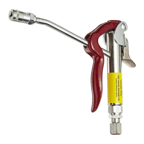
Alemite 6320-3 Service Manual - Page 9
Browse online or download pdf Service Manual for Control Unit Alemite 6320-3. Alemite 6320-3 10 pages. High-pressure control valve

High-Pressure Control Valve
4. Turn the Single-Shot Adjuster 1/8 turn clockwise to
decrease delivery or counterclockwise to increase
delivery.
5. Tighten Locknut (20).
6. Connect the air line to the pump motor.
Control Valve Indications
Continuous product flow
No product flow
Continuous mode does not
function
Single-Shot mode does not
function
Leakage at top and/or bottom of
Body (10)
Leakage at Extension (25)
Leakage at rear end of
Coupler (26)
Leakage around
Locknut (20)
Leakage at top or bottom of Inlet
Adapter (18)
Leakage at Stem (11)
Control Valve Indications
Leakage at front end of
Coupler (26)
* Do not apply PTFE tape to the first two (2) threads. Contamination can occur.
Alemite LLC
Troubleshooting Chart
Control Valve in Static Condition or in Unattached Operation
Possible Problems
1. Foreign material under Valve and Seat
Assembly (16) and/or Single-Shot Valve
(23)
2. Lever adjustment incorrect
Valve not adjusted properly
Single-Shot Adjuster (24) not set correctly Adjust setting
1. Initial tightening not sufficient
2. O-Ring (4) not sealing
3. Crush Gaskets (14) not sealing
Initial tightening not sufficient
Initial tightening not sufficient
1. Initial tightening not sufficient
2. Packing Ring (21) not sealing
1. Initial tightening not sufficient
2. Crush Gasket (19) not sealing
1. O-Ring (6) not sealing
2. Plunger Stem (11) damaged
Control Valve Connected to Fitting
Possible Problems
1. Coupler damaged
2. Coupler to fitting mismatch
3. Foreign or damaged fitting
Changes Since Last Printing
Deleted trademarks
7. Depress the lever partially and observe the amount of
product dispensed.
8. If readjustment is necessary, repeat steps 2 through 5.
9. Depress the lever fully to ensure that the continuous
mode-of-operation is available.
1. Disassemble, clean, and inspect seat
areas. Check mating surfaces and
replace parts as necessary. Locate
and eliminate source of foreign
material.
2. Adjust lever free-play
Adjust setting.
1. Tighten Packing Plug (3) and
Bushing (17)
2. Replace O-Ring (4)
3. Replace Gaskets (14)
1. Tighten Extension into
Body (10)
2. Apply PTFE tape* to Extension
threads
1. Tighten Coupler into Extension (25)
2. Apply PTFE tape* to Extension
threads
1. Tighten Locknut (20)
2. Replace Packing Ring (21)
1. Tighten Inlet Adapter (18)
2. Replace Gasket (19)
1. Replace O-Ring (6)
2. Replace Plunger Stem (11)
1. Replace Coupler (26)
2. Replace fitting and/or Coupler (26)
3. Replace with Alemite fitting
9
SER 6320-3
Solution
Solution
Revision (1-13)
