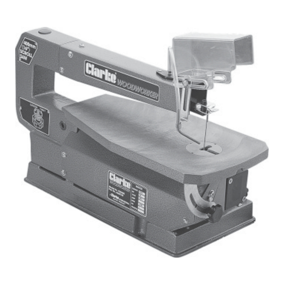
Clarke 6460100 Operating And Maintenance Manual - Page 8
Browse online or download pdf Operating And Maintenance Manual for Saw Clarke 6460100. Clarke 6460100 14 pages. 400mm (16") scroll saw

4. BLADE INSTALLATION / RENEWAL
4.1 Standard Blade (with end pins)
4.1.1 Before installing or removing blades, turn OFF the saw and disconnect it from the
supply. Remove the blade as described in 2. Blade Holder Alignment, above.
NOTE:
Whilst the blade is out of the housings, look at the blade housings closely. You will observe that the blade slots
and pin recesses are made so you can position the blade for cutting from the front, or from the side (see figs.
2 & 3). Cutting from the side is necessary when your workpiece is over 16" long.
IMPORTANT: Side cutting can only be performed when the bevel is set at 0
4.1.2 With the blade teeth pointing DOWNWARDS, slot the new blade into the lower
housing so that the pins on the end of the blade, engage in the recess in the
housing. Holding the blade firmly, apply downward pressure to the upper arm,
whilst slotting the upper end of the blade into the slot in the upper housing,
again, making sure the blade pins correctly engage in the recess in the housing.
4.1.3 Replace the Table Insert, and re-tension to the blade, by turning the tension
knob (17) clockwise until you feel the blade is firm. Check to ensure that the
blade pins are properly seated, top and bottom.
4.2 Plain Blades
A pair of holders is provided allowing the use of plain blades (see fig 5).
In order to install the blades with holders on to the machine, the holders must first be attached, as
follows.
4.2.1 Establish which direction of cut is required. (Normal in-line
or cross cut) This will determine which slots in the holder,
the ends of the blades are to be inserted.
The holder is provided with two slots, at right angles to each
other, and one, hex. socket head grub screw, used for
securing the end of the blade in the slot. It will be necessary
to remove the grub screw from the tapped hole in one
slot, and replace it in the tapped hole in the slot you intend
to use. (Fig. 5 shows a blade prepared for normal 'in line'
cutting).
4.2.2 Remove the side cover (2) by removing the 3 screws securing it
4.2.3 With the two blade holders secured to the blade, and the table insert removed,
lower one end of the blade through the access hole in the table.
Ensure the blades' teeth point DOWNWARDS and FORWARDS. Slot the holder
over the lip on the end of the lower housing, and, applying downward pressure
on the upper arm, slot the upper holder over the lip on the upper housing.
NOTE: Easy access to the lower housing is provided when the side cover is removed.
4.2.4. Replace the table insert, and the side cover, and re-tension the blade by turning
the blade tension knob (17) two full turns clockwise.
9
Fig. 5
O
.
Fig. 5
