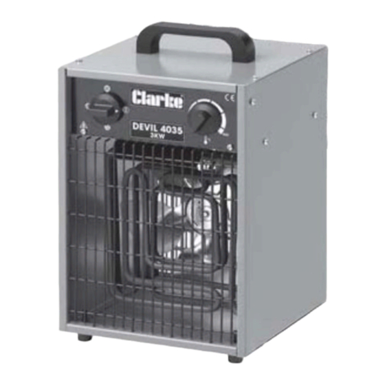
Clarke DEVIL 4035 Operating & Maintenance Manual - Page 4
Browse online or download pdf Operating & Maintenance Manual for Heater Clarke DEVIL 4035. Clarke DEVIL 4035 11 pages. Fan heater
Also for Clarke DEVIL 4035: Operating & Maintenance Instructions (12 pages)

ELECTRICAL CONNECTIONS
Devil 4035
This model is provided with a 13 amp BS 1363 plug, fitted with a 13amp fuse and
MUST be connected to a standard, 230 Volt (50Hz) electrical supply, preferably
through an approved plug , or a suitably fused isolator switch.
IMPORTANT: The wires in the mains lead are coloured in accordance with the
following code:
As the colours of the flexible lead of this appliance may not correspond with the coloured
markings identifying terminals in your plug, or your mains supply, proceed as follows:
•
Connect GREEN & YELLOW coloured cord to plug terminal marked with a letter "E" or
Earth symbol "
•
Connect BROWN cord to terminal marked with a letter "L" or coloured RED.
•
Connect BLUE cord to terminal marked with a letter "N" or coloured BLACK.
Fuse Rating
The fuse in the plug must be replaced with one of the same rating (13 amps) and this re-
placement must be ASTA approved to BS1362.
This appliance is fitted with a plug which is moulded on to the electric cable (i.e. non-
rewireable) please note:
1. The plug must be thrown away if it is cut from the electric cable. There is a danger of
electric shock if it is subsequently inserted into a socket outlet.
2. Never use the plug without the fuse cover fitted.
3. Should you wish to replace a detachable fuse carrier, ensure that the correct
replacement is used (as indicated by marking or colour code).
4. Replacement fuse covers can be obtained from most DIY or electrical stores.
Devils 4055, 4090 & 4115
These machines MUST be connected to a 400 Volt, 3 PHASE 50Hz supply through a suitably
fused isolator switch. It cannot be operated from a single phase supply.
A trailing socket is provided and should be wired as follows:
•
Connect the GREEN or GREEN & YELLOW coloured wire,
to the terminal marked with the letter "E" or Earth
symbol "
"
•
Connect the BLACK wire to the 'N' or Neutral terminal.
•
Connect the Remaining wires to the terminals marked
`L1, L2 and L3.
WARNING! THIS APPLIANCE MUST BE EARTHED
Green & Yellow ........................ Earth
Blue ............................................ Neutral
Brown ........................................ Live
" or coloured GREEN or GREEN & YELLOW.
4
