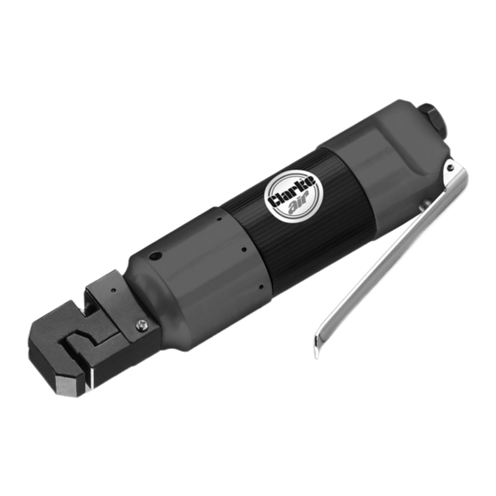
Clarke 3110470 Operating & Maintenance Instructions - Page 9
Browse online or download pdf Operating & Maintenance Instructions for Tools Clarke 3110470. Clarke 3110470 17 pages. 3/16”punch & flange tool

OPERATION
1. Connect the tool to the air supply.
FLANGING
IMPORTANT: If you intend to flange and punch the workpiece, flange it first
and then measure for hole placement. Flanging will change the dimensions
of the workpiece.
1. Measure and cut the workpiece to the correct dimensions.
2. Secure the workpiece in a vice or another appropriate clamping method if
needed.
3. Insert the workpiece into the flanging jaw between the anvil (2) and the
clamp (1). Make sure that the workpiece is flush against the back of both
the anvil and the clamp. Depress the trigger (6) and the anvil will be driven
against the clamp forming a flange.
4. Release the trigger. Slide the punch/flange tool along the edge of the
workpiece to where the anvil (2) and the clamp (1) overlap part of the
workpiece you just flanged. Repeat Step 3.
5. Repeat steps 3 and 4 until the entire flange is finished.
6. Disconnect the tool from the air supply.
PUNCHING
NOTE: The tool head can be rotated 360 degrees. Just manually rotate
the tool head clockwise or counterclockwise within a half
round to make the necessary adjustment.
1. Mark the desired location on the workpiece of each hole you wish to
punch.
2. Insert the edge of the workpiece between the punch die (3)
and punch (4). Make sure that your marks are aligned with the punch die.
3. Depress the trigger (6) and the punch will pierce the workpiece.
4. Align the punch/flange tool with the next mark on the workpiece
and repeat Step 3 until the job is finished.
5. Disconnect the tool from the air supply.
It is recommended that a whip hose with a swivel (not included) be used to
prevent twisting, kinking and resultant wear to the air hose.
Parts & Service: 020 8988 7400 / E-mail: [email protected] or [email protected]
9
