CLAS OM 9381 Manual - Page 8
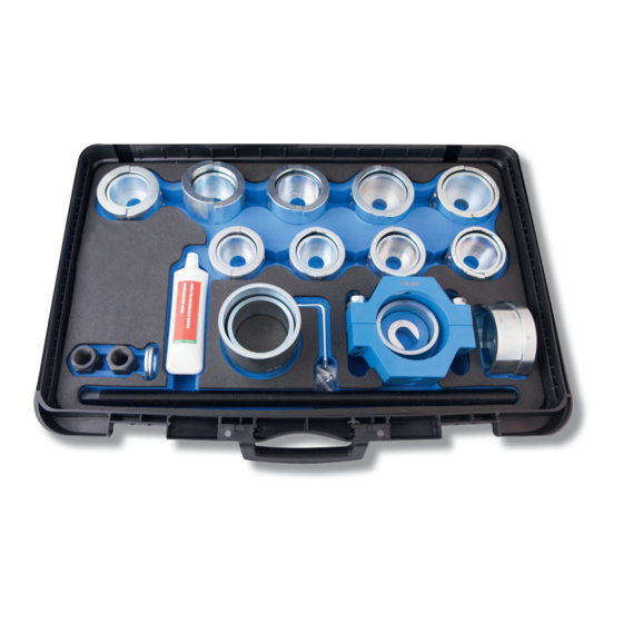
Browse online or download pdf Manual for Tools CLAS OM 9381. CLAS OM 9381 12 pages. Hgv silent-block puller/installation set

OM 9381
5. Place the thrust nut behind the step plate on the thrust screw. Tighten the thrust nut until it protrudes from the thrust
screw by about 2 cm. Act on the thrust nut and at the same time act on the second thrust nut to pull out the bushing
to be removed and placed inside the support socket.
Warning: during disassembly, always check the correct position of all components, correcting it when necessary.
Note: in view of the forces required, at times enormous, especially during removal, we suggest the use of a
hydraulic cylinder. The hydraulic cylinder OH 3512 can be used.
Disassembly using the hollow piston hydraulic cylinder
At rst, follow steps 1 to 5 described in the disassembly point.
Use the hydraulic cylinder with its at side on the step plate. The cylinder's piston should face the opposite direction
of the bushing to be removed.
Place the U-shaped disc and the thrust nut behind the hydraulic cylinder on the spindle and tighten the nut by hand.
Tighten the thrust nut until it protrudes by about 2cm.
Connect the hydraulic pump to the cylinder, actuate it and then take out the bushing to be removed.
Note: the U-shaped spacer included in the supply is required as a lifting extension when used with a hydraulic
cylinder.
Pre-tensioning
1. Choose the semirings and their presser, suitable to the bushing.
2. Insert the semirings into the clamp and secure them together with their screws. Note: the Ø75mm semirings are
used as adapters when using the Ø63/60/58/56 mm semirings; therefore, in order to be used, they must rst
be inserted into the clamp. Subsequently, using the two short screws, you rst secure the Ø75mm semirings from
the outside (the big adapters) in the clamp and then, using the longer screws, you secure the smaller semirings.
3. Now t the bushing to be inserted, well lubricated, into the rst half of the clamp. Note: when positioning the
slot of the bushing to be inserted, always pay attention to insert it between the ends of the semirings. In this way
the bushing will not be distorted during compression. Moreover, the bushing should be positioned approximately
in the center of the clamp so that it will protrude by the same amount at both ends.
4. Place the second half of the clamp and tighten the clamp lock using the nuts until the bushing's slot is fully closed.
The bushing is now pre-tensioned and can be inserted into the support on the vehicle (for example, leaf spring,
stabilizer, driver cab support).
HGV SILENT-BLOCK PULLER/INSTALLATION SET
ASSEMBLY
