1. 4 vibr ation levels
Armstrong Vertical In-Line pumps are designed to meet
vibration levels set by Hydraulic Institute Standard hi Pump
vibration 9.6.4. standard levels are as detailed below:
i nput power @ test conditions–bhp
1
10
7.11
6.10
5.08
4.06
3.04
2.03
0.01
0
0.75
7.5
i nput power @ test conditions–kW
A
X
Y
vertical in–line
1.5 stor age
Pumps not immediately placed into service, or removed from
service and stored, must be properly prepared to prevent
excessive rusting. Pump port protection plates must not be
removed until the pump is ready to connect to the piping.
Rotate the shaft periodically (at least monthly) to keep rotating
element free and bearings fully functional.
For long term storage (longer than 3 months), the pump must
be placed in a vertical position in a dry environment.
Internal rusting can be prevented by removing the plugs at the
top and bottom of the casing and drain or air blow out all water
Commercial pumps Series 4300, 4360 and 4380
100
1000
0.28
0.24
0.20
0.16
0.12
0.08
0.04
0
75
750
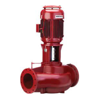
Vertical In–Line pump
to prevent rust buildup or the possibility of freezing. Be sure to
reinstall the plugs when the unit is made operational. Rust-
proofing or packing the casing with moisture absorbing mate-
rial and covering the flanges is acceptable. When returning to
service be sure to remove the drying agent from the pump.
1.6 uncr ating
Armstrong Vertical In-Line pumps are thoroughly inspected
before shipment to assure they meet with your order require-
ments. After removing the pump from the crate, make sure
the equipment is in good order and that all components are
received as called for on the packing list. Any shortages or
damage should be reported immediately. Use extreme care
in handling the unit, placing slings and hooks carefully so that
stress will not be imposed on the pump. Never place cable
slings around the pump shaft. The eye bolts or lifting lugs on
the motor are intended for lifting the motor only and not the
complete unit.
1.7 handling large vil units
One effective way of lifting a large Series 4300 unit from the
shipment pallet following uncovering the unit is to place lifting
hooks through the motor lifting rings or straps around the
upper part of the motor and carefully lift sufficiently to stand
the pump vertically. Lift only enough to remove the pallet then
lower onto a flat surface. The pump and motor unit will free-
stand on the casing ribs. Remove the coupling guard and place
(2) lifting straps through the pump/motor pedestal (one on
each side of the motor shaft) and secure to the lifting device.
With the straps in place, using a spacer bar if necessary to pro-
tect the motor fan cover, the whole assembly can now be lifted
securely and placed in position in the piping.
Secure pallet and lift pump vertical using motor eye-bolts lift only to clear
pallet then sit on the flat surface.
i n sta l la tio n &
o p er at i ng instr uct io ns
5

