For other Armstrong instructions pertaining to 4360D & 4380
pumps please refer to: Installation & Operating – File: 43.64,
Shaft Sleeve Replacement – File: 6042.25, Mechanical Seals
Kits – File: 6040.60"
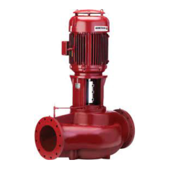
The Series 4360D and 4380 pumps are motor mounted or
"close coupled" type Vertical In Line pumps, on which are
mounted vertical shaft-down ball bearing motors. Each pump
and motor unit is pipe mounted and as such relies on the pip-
ing only for support. The piping support is designed for the
weight of the piping, liquid, pump and motor and other pipe
fittings. The pumping unit should not be independently secured
to the building structure. If the pump is mounted separately to
any structure, the pump must be isolated from the piping with
flexible piping connections. For units with larger motors it is
advisable to install a permanent device for lifting the rotating
assembly out of the pipe mounted casing to service the unit.
BREAKDOWN PROCEDURES:
CAUTION
Exercise extreme care when handling power wiring. Ensure
that the fuses are removed or breaker disconnected in the
power line to the motor. Power disconnect should be within
sight of the pump being serviced and tagged with the reason
for disconnection.
1. ELECTRICAL WIRING
If the pump and/or motor assembly is to be serviced on a
bench, the motor wiring must be disconnected.
2. ISOLATION VALVES
If the system is not drained: Ensure that the suction and
discharge piping isolation valves are closed. Remove drain
plug [105] from the bottom of the casing and drain the
pump.
3. PREPARE ASSEMBLY FOR REMOVAL
Secure the motor [10], by lifting straps, to an overhead
chainfall or similar lifting device. The device must be de-
signed to lift the weight of the unit safely. Raise the lifter to
bring the lifting straps taut. Disconnect the flush/vent tub-
ing assembly and place carefully to one side. Remove the
casing capscrews and washers [103 & 104]. Pry bars may
then be inserted between the casing [100] and adapter
[40]. Care should be taken not to apply pressure to the
outside diameter of the adapter, to prevent possible break-
age, outside pressure should be on the casing only.
4. REMOVE ROTATING ASSEMBLY
The rotating assembly (Motor, adapter and impeller [10,
40 & 80]) may now be lifted out of the casing.
5. ROTATING ASSEMBLY NOTES
The impeller [80] is fastened directly to the motor shaft and
must be removed in order to replace the mechanical seal
assembly [60/62]. This may be accomplished on a safe sur-
face near the installation or, more conveniently, on a work
bench.
6. IMPELLER CAPSCREW
The impeller [80] should be prevented from rotating while
the impeller capscrew [86] is loosened. A heavy screwdriver
may be inserted between the impeller blades to enable the
impeller capscrew [86] to be backed off with a socket
wrench. Remove the impeller capscrew and washer
[86 & 83].
7. PUMP IMPELLER
Using wheel pullers, with the jaws behind the rear shroud of
the impeller [80] (Behind a vane at each side) pull the impel-
ler free of the pump shaft. Impellers that are difficult to re-
move may be loosened by heating the impeller hub with a
torch during the pulling process. Remove the impeller from
the motor shaft. Note the impeller key and shaft sleeve
spacer [71]. Remove both for storage.
8. REMOVE MECHANICAL SEAL FROM MOTOR
SHAFT
The mechanical seal spring usually comes free with the
impeller. The mechanical seal rotating element [62] must be
pried loose with pry bars or screwdrivers, placed under each
side of the seal drive band. Leverage is applied against the
adapter. Once loosened, the seal may be pulled free of the
shaft.
Do not damage the carbon face when removing the rotating
assembly. It may be needed for analysis if seal failure
investigation is required.
9. REMOVE SEAL SEAT FROM ADAPTER
The mechanical seal seat [60], typically O-ring or L-cup
mounted Silicon Carbide material, is pried loose from the
recess in the adapter. If the seat cannot be removed in this
manner, remove the motor capscrews [44] and separate the
adapter [40] from the motor [10]. A screwdriver may then be
used to push the seat out of the adapter from the rear.
10. REMOVE OLD CASING GASKET
The former casing gasket [101] should be scraped from the
casing and adapter, leaving clean surfaces for the new gas-
ket. (A standard putty knife and wire brush are useful for this
purpose)
Page 2 of 3

