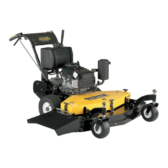
Cub Cadet Commercial G 1336 Operator's And Service Manual - Page 12
Browse online or download pdf Operator's And Service Manual for Lawn Mower Cub Cadet Commercial G 1336. Cub Cadet Commercial G 1336 16 pages. Walk-behind commercial rotary mowers

MAINTENANCE
Figure 10
d. Lift up on the idler bracket with one hand while
removing the belt from the jackshaft pulley with the
other hand. (See Figure 10.)
e. Prop up the side of the mower and slip the belt over
the drive wheel.
f. Slip the new traction drive belt over the drive wheel
and loop it over the jackshaft pulley while lifting up
on the idler bracket.
g. Insert the swivel joints in the holes in the idler
bracket and replace the hairpin cotters.
h. Replace the belt guard and the two nuts.
6. TO CHANGE A SPINDLE ASSEMBLY:
a. Make sure the blade clutch is disengaged.
b. Remove the deck cover.
c. Remove the blade. (See paragraph 1. To Change a
Blade.)
d. Remove the blade drive belts. (See paragraph 3. To
Change the Blade Drive Belts.)
e. Remove the two bolts which hold the pulley bushing
tight in the spindle pulley and thread the bolts into
the other two holes in the bushing.
f. Alternately turn each bolt 1/2 turn clockwise until the
bolts force the pulley off of the bushing.
g. Remove the bushing by tapping a large screw driver
into the slot in the side of the bushing.
h. Remove the key and the pulley.
i. Tip the mower back and block up the front of the
deck.
j. Remove the four bolts and locknuts holding the
spindle assembly to the deck.
k. Remove the spindle assembly.
7. TO CHANGE SPINDLE BEARINGS:
(See the exploded view drawing)
a. Clamp the spindle assembly in a vise with the
grease fitting pointing up.
1. Bend down the tab of the tab lockwasher.
a. Remove the hex jam nut.
b. Obtain a round wooden dowel about 6-inches long
such as a piece of broom handle. Hold this wooden
dowel on top of the spindle and tap it with a hammer
to drive the spindle out of the bearings and the
spindle housing.
c. Pull the seal spacer out of the top seal.
d. Using a large screwdriver, pry the seals out of each
end of the spindle housing. (NOTE: You will destroy
the old seals as you remove them.) As you remove
the old seals, the inner races of the roller bearings
and the internal spacer will fall out of the spindle
housing.
e. Using a bearing puller, remove the outer races from
both ends of the bearing housing. (NOTE: If the
outer races cannot be removed using this procedure,
take the spindle housing to a local machine shop
and let them remove the bearing races.)
f. Clean the old grease out of the spindle housing.
g. Clamp the housing in a vise with the grease fitting
pointing down.
h. Gently drive a new bearing outer race back into the
spindle housing using the wooden dowel. Make
certain that the tapered side of the race faces
outward.
i. Pack one inner race with fresh grease and place it
into the outer race.
j. Press one of the new seals into the spindle housing
by using the wooden dowel, moving around the
circumference of the seal and tapping gently with a
hammer. (NOTE: The metal surface of the seal
should face outward.)
k. Turn the housing over and re-clamp it in the vise with
the grease fitting pointing up.
l. Gently drive the second bearing outer race back into
the spindle housing using the wooden dowel. Make
certain that the tapered side of the race faces
outward.
m. Insert the internal spacer.
n. Pack the second inner race with fresh grease and
place it into the outer race.
o. Press the second new seal into the spindle housing
by using the wooden dowel, moving around the
circumference of the seal and tapping gently with a
hammer. (NOTE: The metal surface of the seal
should face outward.)
p. Coat the spindle with grease and push it up through
the bottom of the spindle housing. The spindle will
pass through the lower seal, an inner race, the
internal spacer, an inner race and the upper seal.
q. Hold the spindle in place and install the seal spacer
down over the spindle and push it into the top seal.
There is a notch on one of the inside edges of the
seal spacer that should be facing up and should be
opposite the side of the spindle with the keyway.
Install the new tab lockwasher with its bent inner tab
pointing down to engage with the notch in the seal
spacer. Install the hex jam nut and tighten it. Bend
up the large tab on the tab lockwasher to hold the
jam nut in place.
12
